


835961-UIM-B-0412
Johnson Controls Unitary Products
9
TABLE 1:
R-410A Saturation Properties
Temp °F
Pressure
PSIG
Temp °F
Pressure
PSIG
Temp °F
Pressure
PSIG
Temp °F
Pressure
PSIG
Temp °F
Pressure
PSIG
45
130
60
170
75
217
90
274
105
341
46
132
61
173
76
221
91
278
106
345
47
135
62
176
77
224
92
282
107
350
48
137
63
179
78
228
93
287
108
355
49
140
64
182
79
232
94
291
109
360
50
142
65
185
80
235
95
295
110
365
51
145
66
188
81
239
96
299
111
370
52
147
67
191
82
243
97
304
112
375
53
150
68
194
83
247
98
308
113
380
54
153
69
197
84
250
99
313
114
385
55
156
70
201
85
254
100
317
115
391
56
158
71
204
86
258
101
322
116
396
57
161
72
207
87
262
102
326.
117
401
58
164
73
211
88
266
103
331
118
407
59
167
74
214
89
270
104
336
119
412
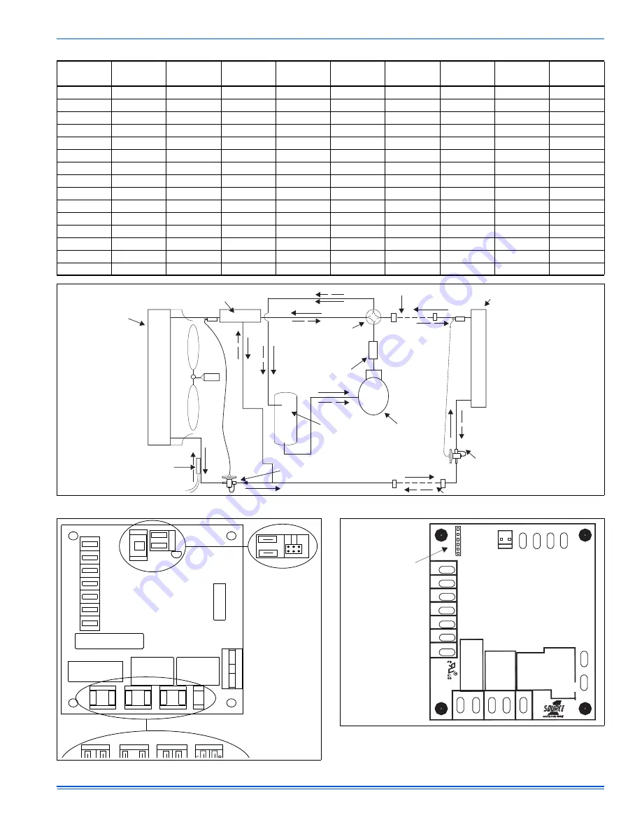
FIGURE 10:
Heat Pump Flow Diagram
CHARGE COMPENSATOR
(Empty in cooling / full in heating)
(Not included in all Units)
FIELD CONNECTED LINE
INDOOR COIL
OUTDOOR
COIL
4-WAY
REVERSING
VALVE
FILTER DRYER
(Solid core)
SUCTION
ACCUMULATOR
LIQUID
SENSOR
COMPRESSOR
BI-FLOW
TXV/CHECK
VALVE (Cooling) **
BI-FLOW
TXV/CHECK
VALVE OR ORIFICE (Heating)
FIGURE 11:
Time/Temp Control Module
9
0
3
0
6
0
Test
RUNTIME
MIN.
SEL
REV
PRESSURE
COMP RLY
DFST
VALVE
OM
XL
XL
R
R
C
C
Y
Y
O
O
W
W
W1/66
W1/66
PRESSURE
SWITCH
DFST
T’STAT
M
M
K2
K1
K3
R3
RUN TIME
30
90
TEST
TEST
RUN TIME
REV
COND.
FA
N
ALTERNATE
CONFIGURATION
ALTERNATE
FIGURE 12:
Demand Defrost Control Module
TEST
AMBIENT
AMBG
COIL
G
COIL
1
2
3
4
COND
FA
N
HIGH
VOL
T
AGE
PRESSURE
M
SWITCH
REV
VALVE
X/L
R
C
Y
O
W
W1/66
X/L
R
C
Y
O
W
W1/66
DEMAND
DEFROST CURVE
SELECTION JUMPER
P


