© 2007 - 2012 Goodman Manufacturing Company, L.P.
5151 San Felipe, Suite 500, Houston, TX 77056
www.goodmanmfg.com - or - www.amana-hac.com
P/N: IO-431A
Date: November 2012
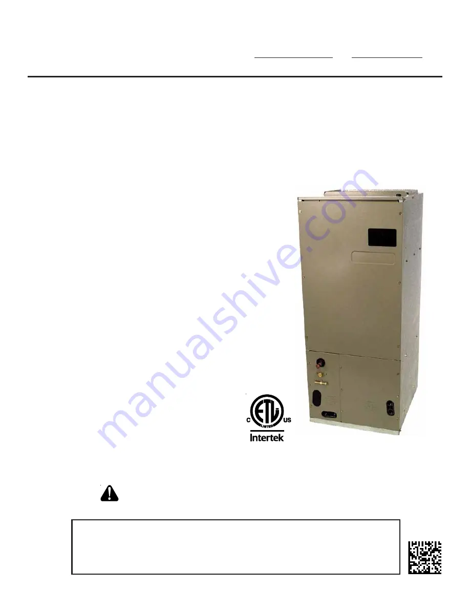
ASPF
AIR HANDLERS
INSTALLATION & OPERATING INSTRUCTIONS
RECOGNIZE THIS SYMBOL AS A SAFETY PRECAUTION.
ATTENTION INSTALLING PERSONNEL
Prior to installation, thoroughly familiarize yourself with this Installation Manual.
Observe all safety warnings. During installation or repair, caution is to be observed.
It is your responsibility to install the product safely and to educate the customer on its safe use.
CONTENTS
Important Safety Instructions ............................................. 2
Shipping Inspection ........................................................... 3
Codes & Regulations ........................................................ 3
Replacement Parts ............................................................ 3
Pre-Installation Instructions ............................................... 3
Location ............................................................................. 3
Ductwork ........................................................................... 3
Return Ductwork .............................................................. 4
Return Air Filters .............................................................. 4
Electric Heat ...................................................................... 4
HKR Installation ................................................................. 4
Electrical Supply Wire and MOP ....................................... 4
Building Electrical Service Inspection .............................. 5
Wire Sizing ...................................................................... 5
Maximum Overcurrent Protection (MOP) ........................ 5
Electrical Connections – Supply Voltage ......................... 5
Air Handler Only (Non-Heat Kit Models) ..................... 5
Air Handler With Non-Circuit Breaker Heat Kits .......... 5
Air Handler With Heat Kits
Containing a Circuit Breaker ................................... 5
Low Voltage Connections ........................................... 6
Refrigerant Lines ............................................................... 6
Tubing Preparation .......................................................... 6
Post Brazing .................................................................... 6
Piping Size ...................................................................... 6
Special Instructions ......................................................... 6
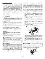
Downflow Conversion ....................................................... 7
Horizontal Conversion ....................................................... 7
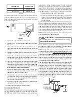
Condensate Removal ........................................................ 8
Achieve 2% Low Leakage Rate ........................................ 9
ASPF Motor ....................................................................... 9
CFM Delivery ................................................................... 9
Start-Up Procedure ........................................................... 9
Regular Maintenance ........................................................ 9
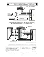
ASPF Thermostat Connections ....................................... 10
Cooling Unit w/Optional Heat Kits
of 10kW and Below ................................................... 10
Cooling Unit w/Optional Heat Kits
of 15kW and Above
and Room Thermostat w/Two Stages of Heat ........... 11
Heat Pump Unit/Optional Heat Kits
of 10kW and Below ................................................... 11
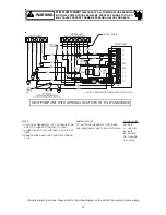
Heat Pump Unit w/Optional Heat Kits
of 15kW and Above ................................................... 12
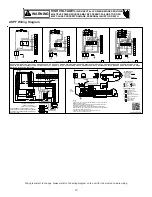
ASPF Wiring Diagram ..................................................... 13
Содержание ASPF Series
Страница 14: ...14 THIS PAGE LEFT INTENTIONALLY BLANK...


