16
Step 4: Assemble the Engine Mount:
Although GSRC had intended to have the engine mount blind-nuts pre-mounted, but in order
to provide the assembler with the most engine mounting flexibility we allow the assembler to
decide the engine mount orientation. We will show how to side-mount an engine. We will be
showing an YS-110FZ®; however, the procedure will be similar for other engines. Take note and
pre-plan for the mounting and thoroughly consider the implications of the muffler and needle
valve locations.
There is ~ 2° right thrust offset built into the fuselage firewall.
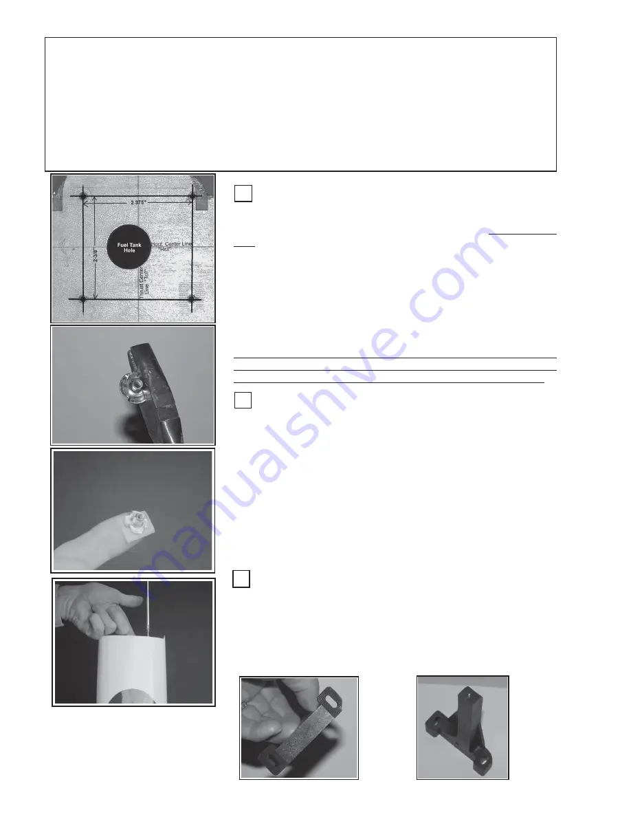
Install Engine Mount Blind-nuts:
Cut the side off one of the blind nuts as shown. This nut goes in the
upper-left corner. Place a washer on one of the engine-mount bolts and
have it and a 7/16” hex-driver at hand. Using a piece of tape, make a
loop and stick it to the end of your index finger. Place a blind-nut on the
tape as shown, left. Orient the blind-nut through the fuel tank hole and
under
one of the firewall bolt holes. Using the engine-bolt & washer,
thread the bolt into the blind-nut. Tighten with the hex-driver to d r a w
the blind-nut into the back side of the firewall. Repeat this process
for the remaining three engine-mount holes.
Note
that the firewall has been marked with the fuel-tank tubing informa-
tion. Refer to the fuel tank assembly step for fuel-tank tubing (port) orientation.
The markings refer to: 1) Muffler or Vent port, 2)
Carburetor port, 3) Fill
port (the 3rd filling port is optional)
Locate the Engine Mounting Holes:
Locate the Horizontal (Hc/l) and Thrust Center Lines (Tc/l). If they
are not visible, measure and draw them in. Draw two (2) parallel lines,
one 1-3/16” to the right and the other 1-3/16” left of the
Thrust Center
Line
.
The distance the two engine mount rails are to be set apart is de-
pendant upon the engine you will be using. Refer to Table 2, (p 46) for
specific engine details. If you engine is not listed, measure the engine
crankcase width just below the engine’s mounting tabs. Add 0.350” to
this dimension (the result will be termed “
A
”) and then divide the number
“
A
” by two (2). The resulting distance will be termed “
B
” Draw two (2)
parallel lines, at “
B
” inches above and below, Hc/l. Where the four lines
cross, center punch and drill 13/64” diameter holes for the blind nuts.
Depending upon the size and type engine you use, you may need to
rotate the entire bolt-hole pattern 2-3 deg. CCW to get the engine inside
the cowl. Do this now if you have any doubts if the engine will fit in.
Modify Upper Mount:
Cut of the corner of the upper engine mount as shown and
check fit on the firewall to be sure the mount will fall within the firewall
perimeter. Temporarily attach the engine mounts using the four
engine mounting bolts and washers. Snug it down tight; however, it
will be removed later to drill the engine mounting holes in the engine
mount rails.
V
C
F
Содержание Bampf 3D Extreme
Страница 50: ...50 ...
Страница 51: ...51 Notes ...
Страница 52: ...52 This Page intensionally left blank ...


