background image

Page 20

2669-RT / 3369-RT / 4069RT

 Operating Instructions & Function Tests

Drive Speed Control

Drive speed is selectable until the platform is elevated above 10 Feet (3 m). When the platform 
is elevated the machine defaults to creep speed and the switch is locked-out (non functioning).

• HIGH SPEED: allows higher drive speeds for travel across flat ground.

SLOW 

SPEED

:

 use for moderate slopes.

Drive Forward

Move

 the MODE SELECT switch in the DRIVE position.

• Squeeze the enable bar and move the control lever away from you.

Test Operation

• Drive speed is proportional and is dependent on the position of the control

lever.

• Releasing the enable bar or returning the control lever to the center position

will stop drive.

• Pressing the EMERGENCY STOP switch will stop drive.

Drive Reverse

• Place the MODE SELECT switch in the DRIVE position.
• Squeeze the enable bar and move the control lever toward you.

Test Operation

• Drive speed is proportional and is dependent on the position of the control

lever.

• Releasing the enable bar or returning the control lever to the center position

will stop drive.

• Pressing the EMERGENCY STOP switch will stop drive.

Brake

• For parking, the brake is automatically applied when the control lever is positioned in 

the neutral (center) position.

Shutdown Procedure

• When finished with the machine, place the platform in the stowed position.

• Park the machine on a level surface.

• Turn the Selector Key Switch to the OFF position and remove the key to

prevent unauthorized use.

• Carefully exit the platform using a constant three (3) point dismount/grip.

• Always put the switch in OFF position when leaving the machine at the end

of the work day.

Speed Select Mode

Torque Select Mode

Torque Mode Control

• HIGH TORQUE: use to drive up or down a steep slope or for careful positioning of


the

machine.

1OP69

 – January 2018

Содержание 2669-RT

Страница 1: ...place Inspection 11 Operating Instructions Function Tests 12 Prestart 12 Starting Engine from Lower Control Panel 13 Starting Engine from Upper Control Box 14 Base Controls Operation and Test 15 Platf...

Страница 2: ...75 m 1 99 m Length stowed with outriggers platform extended 10 2 12 2 14 7 3 12 m 3 7 m 4 5 m 10 2 12 2 14 7 3 12 m 3 7 m 4 5 m 10 2 12 2 14 7 3 12 m 3 7 m 4 5 m Width 69 1 75 m 69 1 75 m 69 1 75 m W...

Страница 3: ...that the operator of the aerial work platform is not alone on the workplace during operation Modifications of this machine from the original design and specifications without written permission fromG...

Страница 4: ...latforms The ANSI SIA A92 5 2006 Manual of Responsibilities is considered a part of this machine and can be found in the manual compartment located at the platform control station To ensure safe use o...

Страница 5: ...allineorapparatuscarryingover300Voltsupto50 000 Volts Onefoot 30 5cm additional clearance is required for every additional 30 000 Volts Observe Minimum Safe Approach Distance This machine is not elect...

Страница 6: ...nd speeds exceed 28 m p h 12 5 m s when the platform is elevated carefully lower the platform and discontinue operation DO NOT increase the surface area of the platform i e cover the rails with tarp o...

Страница 7: ...before moving Be aware of limited sight distance and blind spots when driving or operating Be aware of extended platform position s when moving the machine Reduce travel speed when moving the machine...

Страница 8: ...dily Injury Hazards DO NOT operate the machine when there is a hydraulic fluid or air leak Hydraulic fluid or air under pressure can penetrate and or burn skin All compartments must remain closed and...

Страница 9: ...ols Components Component Locations 1OP69 January 2018 Platform Controls Extension Deck Chassis Platform Emergency Down Lever Battery Disconnect Switch Entry Ladder Lower Controls Lift Cylinders Auto l...
Страница 10: ...the li func on Move the switch to the DOWN posi on to enable the drive func on 5 Start Switch Move the switch to the UP posi on to start engine 6 Horn Bu on Press bu on to sound horn 7 Power Light If...

Страница 11: ...Posi on Moving the switch in this posi on will lower the pla orm 4 Power Light If illuminated the machine has power 5 Hour Meter Indicates total elapsed me of machine opera on 6 Start Switch Move the...

Страница 12: ...rect machine for the job Be aware of workplace conditions and continue to watch for hazards while operating the machine Workplace Inspection Before operating the machine check the workplace for all po...

Страница 13: ...lined in this section This machine shall only be operated by trained and authorized personnel If multiple operators use this machine all must be trained qualified and authorized to use it New operator...

Страница 14: ...ton held press and hold the START Button until the engine starts Release both buttons once the engine starts To protect the starter motor power will cut off to the starter circuit when the starter mot...

Страница 15: ...Release both switches once the engine starts To protect the starter motor power will cut off to the starter circuit when the starter motor has run continuously for approximately 15 seconds without st...

Страница 16: ...nd around the machine for obstructions before operating the machine The machine must have space to allow full elevation of platform Emergency Stop Press the Emergency Stop Switch at any time to stop a...

Страница 17: ...it stops Platform should lift to full height Lower the platform until it stops Scissor assembly should close completely Releasing the switch will stop Lift Lower function Pressing the Emergency Stop S...

Страница 18: ...orm Operations Test Emergency Stop Press the EMERGENCY STOP switch at any time to stop all machine functions Turn switch clockwise to reset Activation of the EMERGENCY STOP switch will apply brakes im...

Страница 19: ...ns Function Tests Operate from Platform Enter the platform through the personnel entry gate Close and secure the entry Start the engine as previously described see page 14 Press the Horn Button if equ...

Страница 20: ...CY STOP switch will stop elevation Lower Platform Place the MODE SELECT switch in the LIFT position Check that no persons or obstructions are in the path of the descending platform Move the control le...

Страница 21: ...e DRIVE position Squeeze the enable bar and move the control lever toward you Test Operation Drive speed is proportional and is dependent on the position of the control lever Releasing the enable bar...

Страница 22: ...CK IS EXTENDED Swing up the handle at the rear of the extension deck to raise the spring loaded pin from the locked position With handle raised push or pull the deck to the desired extended length and...

Страница 23: ...extend and level the machine When the machine is level and ready to operate the outriggers will stop automatically Push and hold the Outrigger Control Switch UP to retract the outriggers The outrigger...

Страница 24: ...ately Fluid leaks under pressure may not always be visible Check for pin hole leaks with a piece of cardboard not your hand NEVER perform work or inspection on the machine with the platform elevated w...

Страница 25: ...ance on this machine and must be done in accordance with the procedures outlined in the service manual Scheduled maintenance inspection checklists are included in this manual for use by qualified serv...

Страница 26: ...o the middle of the sight gauge with platform in the stowed position and outriggers if equipped retracted 2 Hydraulic Filter Filter Element located inside Hydraulic Reservoir Scheduled Maintenance Nor...

Страница 27: ...may cause serious injury blindness and death Repair leaks immediately Fluid leaks under pressure may not always be visible Check for pin hole leaks with a piece of cardboard not your hand NEVER perfo...

Страница 28: ...e or modification Check for missing spring pin retainers _______ Check that all warning and instructional decals are present legible and secure _______ Check the tires for damage _______ Check the tir...

Страница 29: ...for signs of damage broken welds loose bolts improper or makeshift repairs ______ Check that the platform does not drift down with a full load ______ Check all wire connections for tightness and corro...

Страница 30: ...ure Lower Cylinder Pins Secure Lower Beam Mounts tight Rollers Turn Freely Maintenance Locks Secure Operational Base Cover Panels Secure Base Fasteners Tight Bolts Tight FrontAxle Mounting 4WD RearAxl...

Страница 31: ...chine until it has been checked by a trained qualified mechanic Machine functions will not operate Master disconnect turned on Battery properly connected Battery fully charged Fuel level sufficient Ci...

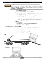
Страница 32: ...ppropriate trailer according to government regulations and company policy Drivers must ensure thatthe vehicleand chains arestrongenoughtoholdtheweightof themachine Seetheserialnumber plate for machine...

Страница 33: ...latform Emergency Stop Switch Test platform control functions Carefully drive the machine off the transport vehicle with the winch attached Note The brakes are automatically released for driving and w...

Страница 34: ...n is retracted and the module doors are closed and secure Remove all loose items from the machine Determine the center of gravity of the machine Attach rigging to the designated lift points only For m...

Страница 35: ...Page 34 2669 RT 3369 RT 4069RT Notes Notes 1OP69 January 2018...

Страница 36: ...2669 RT 3369 RT 4069RT Notes Notes 1OP69 January 2018 Page 35...
Страница 37: ...Global Machinery Group Inc 3428 Bullock Lane San Luis Obispo CA 93401 USA Phone 1 805 303 2066 Toll Free USA Canada 800 303 0499 www goGMG com...

Отзывы: