


4 B 1 - 8
R EA R A X L E
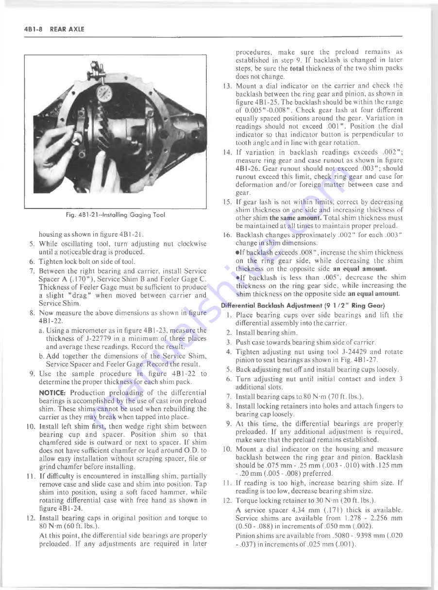
Fig. 4B1 -21 -Installing Gaging Tool
housing as shown in figure 4 B 1 -21.
5. While oscillating tool, turn adjusting nut clockwise
until a noticeable drag is produced.
6. Tighten lock bolt on side of tool.
7. Between the right bearing and carrier, install Service
Spacer A (.1 7 0 " ), Service Shim B and Feeler Gage C.
Thickness of Feeler G age must be sufficient to produce
a slight " d r a g " when moved betw een c a rrie r and
Service Shim.
8. Now measure the above dimensions as shown in figure
4B1-22.
a. Using a micrometer as in figure 4B1-23, measure the
thickness of J-22779 in a minim um of three places
and average these readings. Record the result.
b. Add together the dimensions of the Service Shim,
Service Spacer and Feeler Gage. Record the result.
9. Use th e sam ple pro ced u re in figure 4B1-22 to
determine the proper thickness for each shim pack.
NOTICE:
Production preloading of th e differential
bearings is accomplished by the use of cast iron preload
shim. These shims cannot be used when rebuilding the
carrier as they may break when tapped into place.
10. Install left shim first, then wedge right shim between
bearing cup and spacer. Position shim so t h a t
chamfered side is outward or next to spacer. If shim
does not have sufficient cham fer or lead around O.D. to
allow easy installation without scraping spacer, file or
grind chamfer before installing.
11. If difficulty is encountered in installing shim, partially
remove case and slide case and shim into position. Tap
shim into position, using a soft faced ham m er, while
rotating differential case with free hand as shown in
figure 4B1-24.
12. Install bearing caps in original position and torque to
80 N-m (60 ft. lbs.).
At this point, the differential side bearings are properly
preloaded. If any adjustments are required in later
procedures, m ake sure the preload rem ains as
established in step 9. If backlash is changed in later
steps, be sure the
total
thickness of the two shim packs
does not change.
13. Mount a dial indicator on the carrier and check the
backlash between the ring gear and pinion, as shown in
figure 4B1-25. The backlash should be within the range
of 0.0 0 5 "-0 .0 0 8 " . Check gear lash at four different
equally spaced positions around the gear. Variation in
readings should not exceed .001". Position the dial
indicator so that indicator button is perpendicular to
tooth angle and in line with gear rotation.
14. If variation in backlash readings exceeds .0 0 2 " ;
measure ring gear and case runout as shown in figure
4B1-26. Gear runout should not exceed .0 03"; should
runout exceed this limit, check ring gear and case for
deformation a n d /o r foreign m atter between case and
gear.
15. If gear lash is not within limits, correct by decreasing
shim thickness on one side and increasing thickness of
other shim
the same amount.
Total shim thickness must
be maintained at all times to maintain proper preload.
16. Backlash changes approximately .002" for each .003"
change in shim dimensions.
• I f backlash exceeds .008 ", increase the shim thickness
on the ring gear side, while d ecreasing the shim
thickness on the opposite side
an equal amount.
• I f b acklash is less than .005", d e c re a se the shim
thickness on the ring gear side, while increasing the
shim th ickness on the opposite side
an equal amount.
D iffe re n tia l Backlash A d ju s tm e n t (9 1
I I "
Ring G ear)
1. Place bearing cups over side bearings and lift the
differential assembly into the carrier.
2. Install bearing shim.
3. Push case towards bearing shim side of carrier.
4. Tighten adjusting nut using tool J-24429 and rotate
pinion to seat bearings as shown in Fig. 4 B 1 -27.
5. Back adjusting nut off and install bearing cups loosely.
6. Turn adjusting nut until initial contact and index 3
additional slots.
7. Install bearing caps to 80 N-m (70 ft. lbs.).
8. Install locking retainers into holes and attach fingers to
bearing cap loosely.
9. At this time, the differential bearings are properly
preloaded. If any additional adjustm ent is required,
make sure th at the preload remains established.
10. M ount a dial indicator on the housing and measure
backlash between the ring gear and pinion. Backlash
should be .075 mm - .25 mm (.003 - .010) with .125 mm
- .20 mm (.005 - .008) preferred.
11. If reading is too high, increase bearing shim size. If
reading is too low, decrease bearing shim size.
12. Torque locking retainer to 30 N-m (20 ft. lbs.).
A service spacer 4.34 mm (.171) thick is available.
Service shims are available from 1.278 - 2.256 mm
(0.50 - .088) in increments of .050 mm (.002).
Pinion shims are available from .5080 - .9398 mm (.020
- .037) in increments of .025 mm (.001).
Содержание 1982 Light Duty Truck
Страница 1: ......
Страница 28: ...HEATER 1A 3 Fig lA 2 Heater Control C K Models Fig lA 3 Heater Control G Models...
Страница 37: ...Fig 1A 11 T E E V A L V E A S M TEE AND VALVE C36...
Страница 38: ...HEATER 1A 13 Fig 1A l2 Distributor Ducts G Models Fig 1A l5 Control Assembly G Models...
Страница 39: ...1A 14 HEATER V IE W A V IE W B Fig 1A l7 Control Cable Routing G Models...
Страница 42: ...HEATER 1A 19 Fig 1A 23 Auxiliary Heater Hose Routing...
Страница 56: ...AIR CONDITIONING IB 13 Chart 1B 4 Pressure Cycling CCOT System Diagnosis...
Страница 64: ...Fig 1B 17 C60 System Vacuum Diagram C K Series...
Страница 65: ......
Страница 66: ...Fig 1B 19 C60 Motor Home Chassis Wiring Diagram SWITCH AIR CONDITIONING IB 2 3...
Страница 67: ...IB 24 AIR CONDITIONING Fig IB 20 1 P A C Harness Wiring...
Страница 68: ...AIR CONDITIONING IB 25 VIE W A Fig IB 21 A C Compressor wiring...
Страница 76: ...AIR CONDITIONING IB 33 Fig 1B 26 Compressor Mounting...
Страница 91: ...IB 48 AIR CONDITIONING Fig 1B 59 C K Models Refrigerant Lines L6...
Страница 150: ......
Страница 162: ......
Страница 164: ...2D 2 BODY Fig 2D 4 Typical Utility Vehicle Model...
Страница 165: ...BODY 2D 3 Fig 2D 5 Typical Vans and Sport Vans Models Fig 2D 6 Typical Commercial Cutaway Model Van...
Страница 182: ...2D 20 BODY Fig 2D 51 Rear Door Controls Fig 2D 52 Rear Door Outside Handle and Lock Cylinder...
Страница 193: ...BODY 2D 31 BELTS 3RD SEAT Fig 2D 82 Seat Belt Installation Suburban Driver Seat Suburban...
Страница 194: ...2D 32 BODY Fig 2D 85 Passenger s Bucket Seat Chassis Cab...
Страница 195: ...BODY 2D 33 Fig 2D 88 Rear Bench Seats Suburban...
Страница 196: ...2D 34 BODY Fig 2D 89 CK Utility Seat Attachments...
Страница 197: ...BODY 2D 35 Fig 2D 90 Seat Separator Compartment and Door CK Models...
Страница 198: ...2D 36 BODY MOUNT 1 V MOUNT 2 CK 10 j Fig 2D 91 Body Mounting Chassis Cab Fig 2D 92 Body Mounting Crew Cab...
Страница 222: ......
Страница 223: ...BODY 2D 61 Fig 2D 139 Front Seat Belt Installation...
Страница 228: ......
Страница 234: ......
Страница 252: ...3B2 8 MANUAL STEERING GEAR Fig 3B2 11 Manual Steering Gear Exploded View...
Страница 256: ......
Страница 273: ...POWER STEERING SYSTEM 3B3 17 with LE3 Engine Exc HC4 LE4 LG9 LF4 LS9 LT9 and JB7 HC4 and JB8...
Страница 305: ...STEERING COLUMNS 3B4 17 Fig 3 B 4 1 9 S h ift T u b e A d ju s tm en t 3 S peed M an u al T ransm ission...
Страница 342: ......
Страница 389: ...REAR SUSPENSION 3D 7 Fig 3D 17 Rear Spring Installation C K Models...
Страница 390: ...3D 8 REAR SUSPENSION Fig 3D 20 Rear Spring lnstallation P10 20 Fig 3D 21 Rear Spring lnstallation P30...
Страница 428: ...4 B 1 4 REAR AXLE Fig 4B 8 Gear Tooth Nomenclature Fig 4B 9 G ear Tooth Contact Pattern Check...
Страница 444: ......
Страница 454: ......
Страница 468: ...4 B 5 2 REAR AXLE Fig 4B5 2 Rockwell Assembly...
Страница 480: ...4 B 5 1 4 REAR AXLE...
Страница 482: ...i...
Страница 502: ......
Страница 520: ......
Страница 533: ...Fig 5 5 Front Brake Pipes and Hoses C K Models BRAKES 5 13...
Страница 534: ...Fig 5 6 Front Brake Pipes and Hoses G M odels 5 14 B R A K E S...
Страница 535: ...Fig 5 7 Front Brake Pipes and Hoses P Models BRAKES 5 15...
Страница 536: ...5 16 BRAKES Fig 5 8 Rear Brake Hoses...
Страница 538: ...5 18 BRAKES Fig 5 10 Parking Brake System Typical...
Страница 539: ...BRAKES 5 19...
Страница 552: ...5 32 BRAKES Fig 5 23 Caliper to Stop Clearance BOOT Fig 5 24 Boot Installation Fig 5 25 Sleeve Installation...
Страница 570: ...5 50 BRAKES Fig 5 57 Power Steering Hose Routing C K Models...
Страница 571: ...BRAKES 5 51 Fig 5 58 Power Steering Hose Routing G Models...
Страница 572: ...Fig 5 59 Power Steering H ose Routing P Models 5 52 BRAKES...
Страница 577: ...BRAKES 5 57 4 CONT A SECONDARY DIAPHRAGM B SECONDARY POWER 4 CONT C PRIMARY D Fig 5 5A Service...
Страница 604: ......
Страница 625: ...NOTES ENGINE 6 21...
Страница 626: ......
Страница 629: ...IN LINE 6 6A1 3 OIL PRESSURE SENDING UNIT Fig 6A1 1 In Line Engine Lubrication...
Страница 630: ...6A1 4 IN LINE 6 Fig 6 A l 2 P Series Engine Front Mount...
Страница 631: ...IN LINE 6 6A1 5 Fig 6Al 3 P Series Engine Rear Mount Fig 6 A l 4 C Series Engine Rear Mounts...
Страница 634: ...6A1 8 IN LINE 6 Fig 6Al 7 K Series Engine Rear Mount...
Страница 660: ......
Страница 663: ...SMALL BLOCK 6A4 3 Fig 6A4 T Engine Lubrication...
Страница 664: ...6A4 4 SMALL BLOCK Fig 6A4 2 Engine Lubrication...
Страница 665: ...Fig 6A4 3 P Series Engine Mount Bracket...
Страница 667: ...SMALL BLOCK 6A4 7 Fig 6A 4 5 P Series Engine Front Mount...
Страница 668: ...6A4 8 SMALL BLOCK...
Страница 669: ...SMALL BLOCK 6A4 9 Fig 6A 4 7 K Series Engine Mounts...
Страница 670: ...6A4 10 SMALL BLOCK Fig 6A 4 8 C Series Engine Mounts...
Страница 703: ...MARK IV 6A5 7 Fig 6A 5 6 P Series Engine Front Mount...
Страница 704: ...6A5 8 MARK IV Fig 6 A 5 7 C Series Engine Mounts...
Страница 731: ...6 2 DIESEL 6A7 3...
Страница 760: ...6B 6 ENGINE COOLING Fig 6B 7 A C and A I R Adjustment...
Страница 771: ...ENGINE COOLING 6B 17 Fig 6B 20 Engine O il C o o le r 6 2L Diesel...
Страница 784: ......
Страница 807: ...CARBURETOR MODEL 2SE 6C2 9 Fig 6C2 6 Typical 2SE Carburetor Assembly...
Страница 820: ......
Страница 830: ...6C4 10 CARBURETOR MODEL M4ME M4MC 101368 Fig 6C4 12 M 4M C M 4M E Carburetor Exploded View...
Страница 848: ......
Страница 876: ......
Страница 888: ...6D 12 ENGINE ELECTRICAL Fig 6D 6C Generator Mounting Fig 6D 7C Generator Mounting...
Страница 919: ...ENGINE ELECTRICAL 6D 43...
Страница 923: ...Fig 6D 28D Engine Wiring LE9 LF3 LG9 LS9 D IS T R W IR E ASM E S C CONNECTOR E N G IN E HARNESS...
Страница 934: ...Fig 6D 8E Starter M otor Mounting...
Страница 944: ...i m 1 jry V pvh i HQdVOfcW 0 t V c i v 5 1 J A oh yj Vlk op a j A K j A fmJO Y A u e v c ii gty V AA...
Страница 974: ......
Страница 1011: ...Figure 350C 25A Neutral Engine Running AUTOMATIC TRANSMISSION 350C 11...
Страница 1054: ...Fig 7A 1C 400 Autom atic Transmission Side Cross Section Typical...
Страница 1152: ...700 R4 40 AUTOMATIC TRANSMISSION Figure 700 R4 76 Transmission Assembly Exploded View...
Страница 1162: ......
Страница 1189: ...89MM MANUAL TRANSMISSION 7B3 5 Fig 7 3 4 4 Speed 89mm Exploded View...
Страница 1219: ...CLUTCH 7C 5 Fig 7C 6 C K Truck Clutch Controls...
Страница 1220: ...Fig 7C 7 G Truck Clutch Controls...
Страница 1221: ...CLUTCH 7C 7 Fig 7C 8 P Truck Clutch Controls...
Страница 1234: ...7E 2 TRANSFER CASE Fig 7E 1 Model 208 Transfer Case Cross Section...
Страница 1237: ...M J TRANSFER CASE 7E 5 STRUT ROD SKID PLATES 102757 AUTOMATIC Fig 7E 5 Transfer Case Shifter Skid Plates and Strut Rods...
Страница 1238: ...7E 6 TRANSFER CASE WITH AUTOMATIC TRANSMISSION WITH MANUAL TRANSMISSION Fig 7E 6 Transfer Case Attachments...
Страница 1252: ...7E 20 TRANSFER CASE Fig 7E 39 Transfer Case Attachment Typical...
Страница 1278: ...8A 16 ELECTRICAL BODY AND CHASSIS Fig 8A 11 License Plate Lamps C K Series...
Страница 1280: ...8A 18 ELECTRICAL BODY AND CHASSIS VIEW A VIEW B Fig 8A 15 CK Series Rear Lamp W iring...
Страница 1281: ...ELECTRICAL BODY AND CHASSIS 8A 19 Fig 8A 16 CK Series Auxiliary W iring...
Страница 1289: ...Fig 8B 12 Seat Belt Reminder System Diagnosis SEAT BELT REMINDER LIGHT BUZZER DIAGNOSIS ELECTRICAL AND WIRING 8B 7...
Страница 1290: ...8B 8 ELECTRICAL AND WIRING Fig 8B 13 Seat Belt Reminder System Schematic...
Страница 1292: ......
Страница 1304: ...8C 12 INSTRUMENT PANEL AND GAGES INSTRUMENT CLUSTER KOOO OO K30 TRANSFER CASE I 6 Chart 8C F2 Speedometer Cable Routing...
Страница 1346: ...8C 54 INSTRUMENT PANEL AND GAGES Fig 8C 46 CK Series W iring 3 of 29...
Страница 1351: ...INSTRUMENT PANEL AND GAGES 8C 59 SUBURBAN Fig 8C 51 CK Series W iring 8 of 29...
Страница 1360: ...8C 68 INSTRUMENT PANEL AND GAGES POWCR WINDOWS RPO A 31 FOUR DR Fig 8C 60 C K Series W iring 17 of 29...
Страница 1363: ...INSTRUMENT PANEL AND GAGES 8C 71 ELECTRONIC SPARK CONTROL W ITH RPO L E 9 A U T 0 TRANS Fig 8C 63 CK Series W iring 20 of 29...
Страница 1364: ...8C 72 INSTRUMENT PANEL AND GAGES Fig 8C 64 CK Series W iring 21 of 29...
Страница 1365: ...INSTRUMENT PANEL AND GAGES 8C 73 CAB CRFW CAB CHASSIS Fig 8C 65 CK Series W iring 22 of 29...
Страница 1366: ...8C 74 INSTRUMENT PANEL AND GAGES Fig 8C 66 CK Series W iring 23 of 29...
Страница 1372: ...8C 80 INSTRUMENT PANEL AND GAGES RT SIDE MARKER L W LT SIOE MARKER FORWARD LAMP RPO V 22 Fig 8C 72 CK Series W iring 29 of 29...
Страница 1374: ...8C 82 INSTRUMENT PANEL AND GAGES Fig 8C 74 G Series W iring 2 of 19...
Страница 1375: ...INSTRUMENT PANEL AND GAGES 8C 83 Fig 8C 75 G Series W iring 3 of 19...
Страница 1376: ...8C 84 INSTRUMENT PANEL AND GAGES Fig 8C 76 G Series W iring 4 of 19...
Страница 1379: ...INSTRUMENT PANEL AND GAGES 8C 87 Fig 8C 79 G Series W iring 7 of 19...
Страница 1383: ...INSTRUMENT PANEL AND GAGES 8C 91 Fig 8C 83 G Series W iring 11 o f 19...
Страница 1384: ...8C 92 INSTRUMENT PANEL AND GAGES BUS BARGWO Fig 8C 84 G Series W iring 12 of 19...
Страница 1386: ...8C 94 INSTRUMENT PANEL AND GAGES 2P IN K 7 h B INSTRUMENT PANEL HARNESS DOME LP S W WIRE Fig 8C 86 G Series W iring 14 of 19...
Страница 1387: ...INSTRUMENT PANEL AND GAGES 8C 95 UNLOCK UP l e f t frt SPKR CHANNEL A Fig 8C 87 G Series W iring 15 of 19...
Страница 1390: ...8C 98 INSTRUMENT PANEL AND GAGES Fig 8C 90 G Series W iring 18 of 19...
Страница 1391: ...INSTRUMENT PANEL AND GAGES 8C 99 Fig 8C 91 G Series W iring 19 of 19...
Страница 1392: ...8C 100 INSTRUMENT PANEL AND GAGES Fig 8C 92 P Series W iring 1 of 11...
Страница 1393: ...INSTRUMENT PANEL AND GAGES 8C 101 Fig 8C 93 P Series W iring 2 of 11...
Страница 1395: ...INSTRUMENT PANEL AND GAGES 8C 103 RADIATOR LOW COOLANT LEVEL SENSOR 0 YEL BLK 60 SXL Fig 8C 95 P Series W iring 4 of 11...
Страница 1396: ...8C 104 INSTRUMENT PANEL AND GAGES Fig 8C 96 P Series W iring 5 of 11...
Страница 1398: ...8C 106 INSTRUMENT PANEL AND GAGES PROVISIONS FOR SIDE MARKER LP HIGH LOW SEAM Fig 8C 98 P Series W iring 7 of 11...
Страница 1399: ...INSTRUMENT PANEL AND GAGES 8C 107 Fig 8C 99 P Series W iring 8 of 11...
Страница 1400: ...8C 108 INSTRUMENT PANEL AND GAGES PROVISIONS FOR SIDE MARKER LP Fig 8C 100 P Series W iring 9 of 11...
Страница 1401: ...INSTRUMENT PANEL AND GAGES 8C 109 START RUN OF LOCK ACC Fig 8C 101 P Series W iring 10 of 11...
Страница 1402: ...8C 110 INSTRUMENT PANEL AND GAGES IGN SW START OFF LOCK P 3 0 0 3 2 D RIVE Fig 8C 102 P Series W iring 11 of 11...
Страница 1415: ...ACCESSORIES 9 13 RADIO NOISE BLOWER MOTOR Fig 9 6R Radio Diagnosis Chart B...
Страница 1416: ...9 14 ACCESSORIES D E A D R A D IO A M R A D IO I Fig 9 7R Radio Diagnosis Chart C...
Страница 1417: ...ACCESSORIES 9 15 DEAD RADIO AM FM RADIO Fig 9 8R Radio Diagnosis Chart D...
Страница 1435: ...t f l i t 1...


