background image

Troubleshooting 12

0020200967_00 SUSTAIN ..s Installation and maintenance instructions

25

1

2

3

5

4

A

B

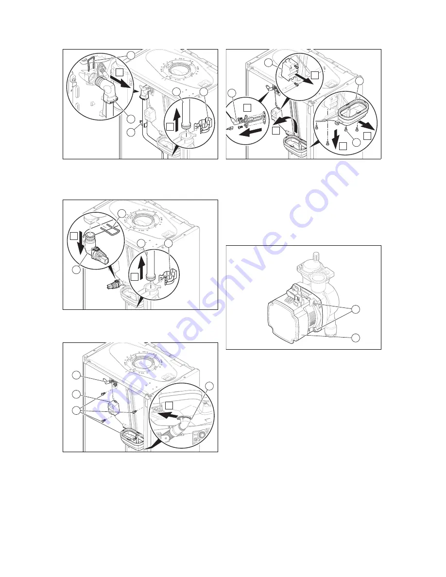
4.

Remove the temperature sensor

(3)

.

5.

Remove the upper clip

(1)

.

6.

Remove the lower clip

(4)

.

7.

Remove the supply pipe

(5)

.

2

2

3

B

1

A

8.

Remove the upper clip

(1)

.

9.

Remove the lower clip

(3)

.

10. Remove the return pipe

(2)

.

1

A

2

3

4

11. Remove the clip underneath the condensate tray

(1)

.

12. Undo the four screws

(2)

.

1

3

2

4

A

C

B

D

E

13. Lift the heat exchanger up slightly and remove it to-

gether with the condensate tray

(1)

.

14. Undo the four screws

(3)

.

15. Remove the condensate tray.
16. Remove the ignition transformer

(2)

.

17. Use the bolts to secure the condensate tray to the new

heat exchanger.

18. Install the new heat exchanger in reverse order.

12.6.4 Replacing the pump head

1

2

1.

Disconnect the pump cable from the electronics box.

2.

Undo the four bolts

(1)

.

3.

Remove the pump head

(2)

.

4.

Replace the O-ring.

5.

Use four screws to secure the new pump head.

6.

Connect the pump cable to the electronics box.

12.6.5 Replacing the expansion vessel

1.

Drain the product. (

Page 23)

Содержание ENERGY 12s-A

Страница 1: ...The energy you need Installation and main tenance instructions SUSTAIN s SUSTAIN 12s A H GB SUSTAIN 15s A H GB SUSTAIN 18s A H GB GB ...

Страница 2: ...ing the heating installation 18 7 8 Filling the condensate siphon 18 7 9 Checking and adjusting the gas settings 18 7 10 Checking function and leak tightness 20 8 Adapting the unit to the heating installation 20 8 1 Burner anti cycling time 20 8 2 Setting the pump output 20 8 3 Setting the bypass valve 21 9 Adjusting the hot water temperature 21 9 1 Setting the hot water temperature 21 10 Handing ...

Страница 3: ...ypes follow the specifications in these in structions Intended use includes the following observance of accompanying operating installation and servicing instructions for the product and any other system compon ents installing and fitting the product in accord ance with the product and system approval compliance with all inspection and main tenance conditions listed in the instruc tions Intended u...

Страница 4: ...Secure against being switched back on again Wait for at least 3 minutes until the con densers have discharged 1 4 7 Risk of death due to lack of safety devices The schematic drawings included in this doc ument do not show all safety devices re quired for correct installation Install the necessary safety devices in the system Observe the applicable national and inter national laws standards and gui...

Страница 5: ...ng and flue gas analysis Installers shall carryout a full site risk as sessment and put into place all necessary steps and procedures to comply with Health and safety at work act and ensure safety of themselves and others with regard to manual handling and working at height requirements During the appliance installation and any subsequent work such as the replacement of major parts it will be nece...

Страница 6: ...70kW BS 5440 2 Flueing and ventilation for gas appliances of rated input not exceeding 70kW 1st 2nd and 3rd family gases BS 5449 Forced circulation hot water sys tems up to 45kW BS EN 6798 Installation maintenance of gas fired hot water boilers of rated input not exceeding 70kW net BS 5482 Part 1 Domestic butane and propane gas burning installations Institute of Gas Engineers Publications IGE UP 1...

Страница 7: ...its year of production For quality control purposes 5th and 6th digits week of production For identification purposes 7th to 16th digits product article number For quality control purposes 17th to 20th digits place of manufacture SUSTAIN s Product description 2H G20 20 mbar 2 kPa Factory setting for type of gas and gas connection pressure Cat Approved gas category Condensing techno logy Efficiency...

Страница 8: ...nsure your movements are coordinated during lifting Avoid bending your upper body do not lean forwards or to the side Wear suitable non slip protective gloves in order to pro tect your hands against sharp edges Ensure that you are carrying the load securely If required get somebody to assist you in this 4 1 2 Unloading the box from the delivery van It is recommended that two people lift the unit t...

Страница 9: ...ombustible materials 4 7 Using the installation template Use the installation template to ascertain the locations at which you need to drill holes and make breakthroughs 4 8 Wall mounting the product Note If you are using the rear air flue gas connection install the flue pipe before you wall mount the product B A 1 Check whether the wall has sufficient load bearing ca pacity to bear the operationa...

Страница 10: ...ng forwards at the bottom edge 4 Lift the front casing upwards from the bracket 4 9 2 Fitting the front panel Refit the components in the reverse order 4 10 Removing installing the side section 4 10 1 Removing the side section Caution Risk of material damage caused by mech anical deformation Removing both side sections may cause mechanical distortion in the product which may cause damage to the pi...

Страница 11: ...diffusion tight plastic pipes in the heating installation separate the system by installing an external heat ex changer between the boiler and the heat ing installation Caution Risk of material damage due to heat trans fer during soldering Do not solder the connection pieces if the connection pieces are screwed to the service valves Note We recommend that you provide the water pipes to the boiler ...

Страница 12: ...he supplied drain hose 2 for this Connect condensate drain pipework 21 5 mm not in cluded in the scope of delivery 3 to the drain hose 2 During installation remove all burs from inside of cut pipe work and avoid excessive adhesive which may trap small pockets of water close to the pipe wall which can freeze and build into a larger ice plug As with other pipe work insulate the condensate dis charge...

Страница 13: ...IN 15s A H GB 5 m SUSTAIN 18s A H GB 5 m 5 5 1 4 Air flue gas system via separate pipes L2 L1 Each line that runs through a wall and whose temperature exceeds the room temperature by 60 C must be equipped with thermal insulation where it passes through the wall This may be carried out using suitable insulating material with a strength of 10 mm and thermal conductivity of λ 0 04 W mK e g glass wool...

Страница 14: ...6 4 Establishing the power supply 1 1 Observe all valid regulations 2 Ensure that the rated mains voltage is 230 V 3 Set up a fixed connection and install a partition with a contact opening of at least 3 mm e g fuses or power switches 4 Provide one common electricity supply for the boiler and for the corresponding controller Power supply Single phase 230 V 50 Hz Fuse protection 3 A 5 Open the elec...

Страница 15: ... the button for 7 seconds is shown in the display 2 Press the or button to set the value The access code 96 is reserved for the competent person The access code 35 is reserved for the customer service 3 Press the button to confirm is shown in the display 6 1 2 Setting a diagnostics code 1 Press the or button to select the diagnostics code 2 Press the button to confirm The value and or status of th...

Страница 16: ...commissioning checklist in the appendix Page 40 of the installation instructions must be filled in and stored carefully along with the unit s documentation Carry out the initial start up using the first commission ing checklist in the appendix Fill out and sign the first commissioning checklist 7 2 Checking the type of gas Make sure that the product is set up correctly by checking the type of gas ...

Страница 17: ... of 8 5 Caution Risk of material damage if the heating water is treated with unsuitable additives Unsuitable additives may cause changes in the components noises in heating mode and possibly subsequent damage Do not use any unsuitable frost and cor rosion protection agents biocides or seal ants No incompatibility with our products has been detected to date with proper use of the following additive...

Страница 18: ...her all connections are leak tight Conditions If the noise persists in the boiler Purge the product again by activating check programme P 07 and then P 06 Check programmes Overview Page 28 7 8 Filling the condensate siphon C 2 3 1 A B 1 Unclip the lower section of the siphon 1 from the up per section of the siphon 2 2 Remove the float 3 3 Fill the lower section of the siphon with water up to 10 mm...

Страница 19: ...O or CO2 in the fresh air search for a leak in the flue gas system or for the flue gas recircula tion 6 Eliminate the damage 7 Repeat the above mentioned test to determine if the fresh air contains CO or CO2 8 If you cannot eliminate the damage you must not start up the boiler 7 9 3 Thoroughly flushing the heating installation hot 1 Operate the appliance until the boiler and the heating system are...

Страница 20: ...18 5 Activate the display for the current operating status Page 15 Status codes Overview Page 32 If the product is working correctly the display shows S 04 7 10 2 Checking the hot water generation 1 Activate the hot water handling mode on the user inter face 2 Open a hot water valve completely 3 Activate the display for the current operating status Page 15 Status codes Overview Page 32 If the prod...

Страница 21: ...radiators or radiator valves Fit the front panel Page 10 9 Adjusting the hot water temperature You can reset change the system parameters section Using diagnostics codes Overview of diagnostics codes Page 28 9 1 Setting the hot water temperature Danger Risk of death from Legionella Legionella multiply at temperatures below 60 C Ensure that the operator is familiar with all of the Anti legionella m...

Страница 22: ...If you require spare parts for maintenance or repair work use only Glow worm original spare parts 11 3 Removing the gas air mixture unit Note The gas air mixture unit consists of three main components Ventilator Gas valve Burner cover 1 Switch off the product via the main switch 2 Close the gas isolator cock 3 Remove the front casing Page 10 B A 1 C 2 4 Push the clip 1 upwards 5 Remove the flue pi...

Страница 23: ...hat the seal 5 is free from damage If necessary replace the seal 11 7 Cleaning the condensate siphon C 2 3 1 A B 1 Unclip the lower section of the siphon 1 from the up per section of the siphon 2 2 Remove the float 3 3 Flush out the float and lower section of the siphon with water 4 Fill the lower section of the siphon with water up to 10 mm below the upper edge of the condensate drain pipe work 5...

Страница 24: ... memory to gether with the time at which the respective fault occurred and after 24 hours with the number of days Hold the button down for more than 7 seconds Overview of fault codes Page 33 Press the button to exit this menu 12 3 Deleting the fault memory 1 Delete the fault memory using the diagnostics code d 94 2 Set the diagnostics code Page 15 Overview of diagnostics codes Page 28 12 4 Resetti...

Страница 25: ...ft the heat exchanger up slightly and remove it to gether with the condensate tray 1 14 Undo the four screws 3 15 Remove the condensate tray 16 Remove the ignition transformer 2 17 Use the bolts to secure the condensate tray to the new heat exchanger 18 Install the new heat exchanger in reverse order 12 6 4 Replacing the pump head 1 2 1 Disconnect the pump cable from the electronics box 2 Undo the...

Страница 26: ... box Page 14 2 Pull all of the plugs out from the PCB 3 Undo the clips on the PCB 4 Remove the PCB 5 Install the new PCB in such a way that it clicks into the groove at the bottom and into the clip at the top 6 Plug in the PCB plugs 7 Close the electronics box 12 6 7 Replacing the PCB for the user interface B C C D A A 1 Open the electronics box Page 14 2 Pull the plug out of the PCB 3 Undo the cl...

Страница 27: ...lip 1 12 7 Completing repair work Check that the product functions correctly and is leak tight Page 20 13 Decommissioning the product Switch off the product Disconnect the product from the power mains Close the gas isolator cock Close the cold water stop cock Drain the product Page 23 14 Customer service For contact details for our customer service department you can write to the address that is p...

Страница 28: ...ing function is activated The function is activated for 15 minutes P 06 Purging the heating circuit The diverter valve is moved to the heating position The function is activated in the heating circuit for 15 minutes The pump runs and stops at regular intervals If required this function can be manually switched off P 07 Purging the hot water circuit The function is activated in the small hot water ...

Страница 29: ...eating circuit s shunt pump Current value off on Not adjustable d 13 Status of the hot water circuit s circulation pump Current value off on Not adjustable d 14 Operating mode of the modulating pump 0 5 0 variable rotational speed auto 1 2 3 4 5 Fixed rotational speeds Section Setting the pump output 0 Adjustable d 15 Pump speed Current value Not adjustable d 16 Status of the 24 V room thermostat ...

Страница 30: ... Cylinder charging pump 4 Extractor hood 5 External solenoid valve 6 External fault message 7 Solar pump omitted 8 eBUS remote control 9 Legionella protection pump 10 Solar valve 1 Adjustable d 28 Function of relay 2 multi functional module 1 10 1 Circulation pump 2 External pump 3 Cylinder charging pump 4 Extractor hood 5 External solenoid valve 6 External fault message 7 Solar pump omitted 8 eBU...

Страница 31: ...ff Function deactivated on Function activated 1 Adjustable d 67 Remaining burner anti cycling time setting un der d 02 Current value min Not adjustable d 68 Number of unsuccessful ignitions at 1st attempt Current value Not adjustable d 69 Number of unsuccessful ignitions at 2nd attempt Current value Not adjustable d 70 Operation of the diverter valve 0 2 0 Normal operating mode DHW and heating mod...

Страница 32: ...ce PCB Adjustable d 96 Default setting reset 0 No 1 Yes Adjustable d 128 Heating minimum target value 10 75 1 10 Adjustable d 129 Minimum hot water tar get value 35 com bination unit 45 pure boiler 60 1 35 combination unit 45 pure boiler Adjustable C Status codes Overview Note Since the code table is used for various products some codes may not be visible for the product in question Status code Me...

Страница 33: ... Product purging active S 91 Maintenance Demo mode S 96 Automatic test programme Return temperature sensor heating demands blocked S 97 Automatic test programme Water pressure sensor heating demands blocked S 98 Automatic test programme Return temperature sensor heating demands blocked S 99 Internal automatic test programmes S 108 Purging the combustion chamber fan in operation S 109 Product s sta...

Страница 34: ... switch fault Pressure monitor has not switched or has switched at a fan speed value that is too high insufficient air supply Pressure monitor plug not correctly plugged in pressure monitor defective hose removed from between the pressure monitor and silencer air flue pipe blocked F 49 eBUS fault Voltage too low Short circuit on eBUS eBUS overload or two power supplies with different polarities on...

Страница 35: ...eturn temperature sensors signalling implausible values Flow and return temperature sensors have been inverted flow and return temperature sensors have not been correctly installed F 85 Fault Temperature sensor The flow and or return temperature sensors have been installed on the same pipe incorrect pipe Temperature sensor not connected or is connected incorrectly F 86 Fault Underfloor heating con...

Страница 36: ...N 24V RT BUS Burner off RT 230Vac X1 FUS X106 X32 X90 X12 X35 X21 L N RT 230Vac N L X1 1 3 4 1 3 1 2 3 eBUS Burner off X106 M 5 4 2 1 2 1 2 1 N L L 24V 230V 24V 230V 2 7 8 10 9 1 4 3 5 6 12 11 1 Main PCB 2 Interface PCB 3 Control system 4 Temperature sensor in the heating flow 5 Temperature sensor in the heating return 6 Fan 7 Gas valve 8 Pressure sensor 9 Ionisation electrode 10 Heating pump 11 I...

Страница 37: ...ections and other connections are seated correctly and correct these if necessary X X 7 Close the gas isolator cock and the service valves X X 8 Drain the product on the water side Check the pre charge pressure of the expansion vessel and if required top up the expansion vessel approx 0 03 MPa 0 3 bar below the system filling pressure X 9 Remove the gas air mixture unit X 10 Check the seals in the...

Страница 38: ...pipes 75 mm E Below eaves 200 mm F Below balconies or car port roofs 200 mm G From vertical wastewater pipes or down pipes 150 mm H From external or internal corners 200 mm I Above floors roofs or balconies 300 mm J From a surface facing a terminal 600 mm K From a terminal facing a terminal 1 200 mm L From an opening in the car port e g door window which leads into the dwelling 1 200 mm M Vertical...

Страница 39: ...m without affecting the performance of the boiler In order to ensure that the condensate vapour plume does not damage adjacent surfaces the terminal should be exten ded as shown Dimension H This clearance may be reduced to 25 mm without adversely affecting the performance of the boiler How ever in order to ensure that the condensate vapour plume does not damage adjacent surfaces a clearance of 300...

Страница 40: ... SUSTAIN s 0020200967_00 H Commissioning Checklist Heating and Hotwater Industry Council HHIC www centralheating co uk Benchmark Commissioning and Servicing Section It is a requirement that the boiler is installed and commissioned to the completed in full ...

Страница 41: ...th the appropriate Building Regulations and then handed to the customer to keep for future reference GAS BOILER SYSTEM COMMISSIONING CHECKLIST CONTROLS Optimum start control Fitted Fitted Fitted Fitted ALL SYSTEMS Yes Yes CENTRAL HEATING MODE OR mbar OR mbar COMBINATION BOILERS ONLY Yes Yes DOMESTIC HOT WATER MODE OR mbar OR mbar Yes Temperature CONDENSING BOILERS ONLY Yes ALL INSTALLATIONS AND Ra...

Страница 42: ...g system is serviced regularly and that the appropriate Service Interval Record is completed Service Provider SERVICE RECORD SERVICE 01 AND AND SERVICE 02 AND AND SERVICE 03 AND AND SERVICE 04 AND AND SERVICE 05 AND AND SERVICE 06 AND AND SERVICE 07 AND AND SERVICE 08 AND AND SERVICE 09 AND AND SERVICE 10 AND AND ...

Страница 43: ...specify how to set boiler to minimum rate contact Technical Helpline for advice CHECK CO AND COMBUSTION RATIO AT MINIMUM RATE With boiler still set at minimum rate insert analyser probe into flue gas sampling point Allow readings to stabilise before recording NOTE If no flue gas sampling point is present and the correct procedure is not specified in the manual consult boiler manufacturer for guida...

Страница 44: ... 15 9 kW 5 2 19 1 kW Effective output range P at 80 60 C 4 5 12 3 kW 4 5 15 2 kW 5 0 18 3 kW Domestic hot water heat output P 4 4 15 0 kW 4 4 18 0 kW 4 9 25 2 kW Maximum heat input heating Q max 12 3 kW 15 3 kW 18 4 kW Minimum heat input heat ing Q min 4 5 kW 4 5 kW 5 0 kW Maximum heat input hot water Q max 15 3 kW 18 4 kW 25 7 kW Minimum heat input hot water Q min 4 5 kW 4 5 kW 5 0 kW Technical d...

Страница 45: ... C53 Nominal efficiency at 80 60 C 99 6 99 6 99 6 Nominal efficiency at 50 30 C 104 0 104 0 104 0 Nominal efficiency at 40 30 C 106 0 106 0 106 0 Nominal efficiency in partial load operation 30 at 40 30 C 108 5 108 5 108 5 NOx class 5 5 5 Product dimensions width 390 mm 390 mm 390 mm Product dimensions depth 280 mm 280 mm 280 mm Product dimensions height 700 mm 700 mm 700 mm Net weight 31 kg 31 kg...

Страница 46: ...operator 21 High efficiency pump 20 High efficiency pump output 20 I Identification plate 7 If you smell gas 3 Inspection work 21 37 Installation site 4 Intended use 3 L Leak detection spray 5 M Mains connection 14 Maintenance work 21 37 Minimum clearance 9 P Power supply 14 Preparing the repair work 24 Preparing repair work 24 Pressure sensor 27 Pump head 25 R Regulations 5 Removing the air intak...

Страница 47: ......

Страница 48: ...am Road Belper Derbyshire DE56 1JQ Telephone 016 34 29 23 00 Fax 016 34 29 01 66 Technical helpline 084 4 736 00 59 After sales service 017 73 82 81 00 www glow worm co uk We reserve the right to make technical changes 0020200967 0020200967_00 26 05 2015 10 05 53 ...

Отзывы: