


Supplied By www.heating spares.co Tel. 0161 620 6677
15
220459C
8 Commissioning
8.1 All Systems
Make sure that the system has been thoroughly flushed
out with cold water without the pump in place.
Refit the pump, fill the system with water, ensuring that
all air is properly vented from the system and pump.
Before operating the boiler check that all external
controls are calling for heat.
8.2 Sealed Water Systems Only
Flush the whole of the system with cold water without
the pump in place. Refit the pump and fill until the
pressure gauge registers 1.5bar (21.5lbf/in
2
). Clear any
air locks and check for water soundness.
Check the operation of the safety valve, by allowing the
water pressure to rise until the valve opens. The valve
should open /- 0.3 bar (+/-4.3lbf/in
2
) of the 3bar
preset pressure. Where this is not possible conduct a
manual check and test.
Release cold water to initial system design pressure.
The set pointer on the pressure gauge should be set to
coincide with the indicating pointer.
8.3 Initial Lighting and Testing
Refit the outer case, see diagram 5.1.
Identify the controls by reference to diagram 8.1.
Turn boiler thermostat to “O” the Off position.
Remove the gas pressure test point screws “K” and fit a
suitable pressure gauge.
Turn the electrical supply on and check that the pump is
working.
OPEN ALL WINDOWS AND EXTINGUISH ANY
NAKED LIGHTS, PIPES, CIGARETTES etc.
Turn on the main gas supply and purge in accordance
with the current issue of BS6891.
Turn boiler gas service cock “J” to On.
Depress control button “B”, keep pressed in and at the
same time operate the piezo unit button “C” until the
pilot burner lights. After the pilot burner lights keep the
button “B” depressed for about 15 seconds. If the pilot
fails to stay alight a safety device prevents immediate
relighting. Do not attempt to relight until the safety
device has reset. Check the length of the pilot flame, it
should envelop the thermocouple tip as shown in
diagram 10.3. The pilot rate can be adjusted by turning
screw “H” having first removed the gas valve cover by
releasing the screw. Test pilot supply connection for gas
soundness with a suitable leak detection fluid.
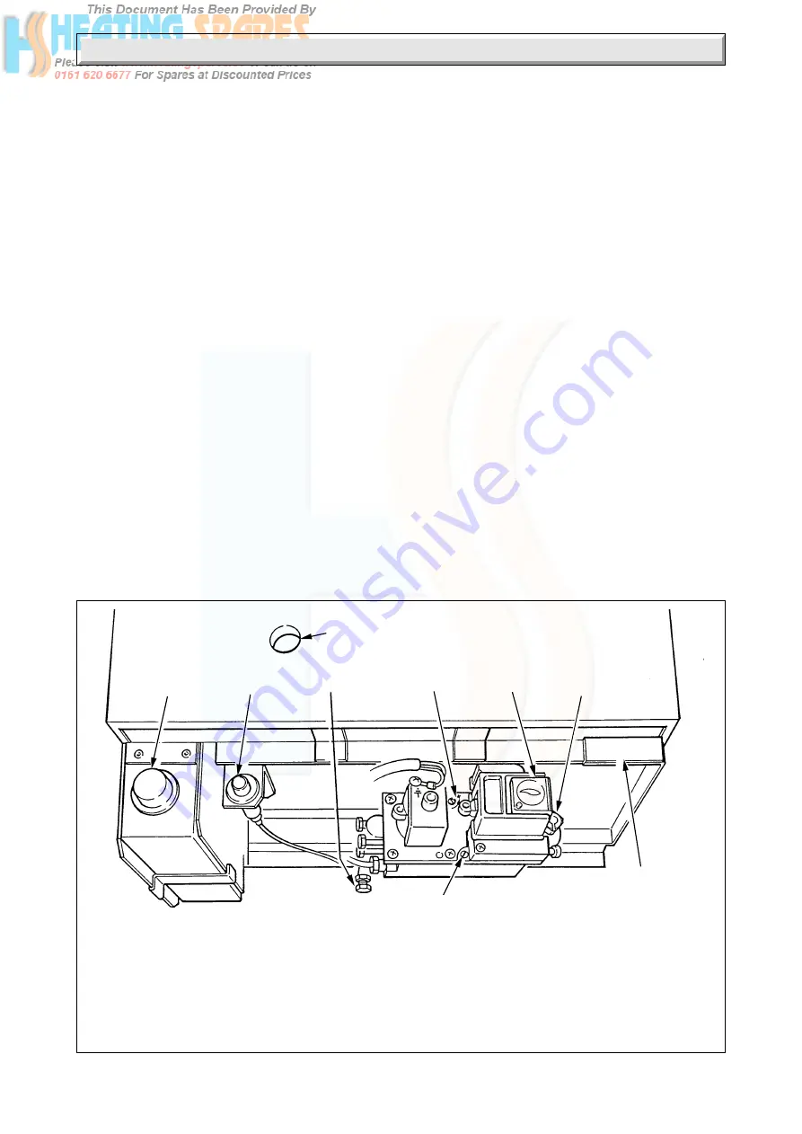
BOILER CONTROLS
Diagram 8.1
A. BOILER THERMOSTAT
H. GAS RATE ADJUSTMENT SCREW
B. GAS CONTROL KNOB
H.
(UNDER COVER SCREW)
C. IGNITION BUTTON
J. GAS SERVICE COCK
G. VIEWING WINDOW
K. PRESSURE TEST POINT
L. PILOT BURNER
L.
ADJUSTMENT SCREW
J. (SHOWN OFF)
B
H
G
L
MODEL AND
SERIAL NUMBER
A
C
K
2416


