12
5 Water System - Heating
5.1 General
This boiler is designed for use as part of a sealed water
central heating system with fully pumped circulation. The
pump, expansion vessel and associated safety devices are all
fitted within the boiler.
5.2 Safety Valve
The safety valve is an integral part of the boiler and it cannot
be adjusted.The pipe from the safety discharge valve must
not discharge above an entrance, window or any type of
public access area.
5.3 Expansion Vessel
The boiler has an integral expansion vessel with a capacity of
8 litres (1.76 gallons), with a charge pressure of 0.5bar.
NOTE:
The expansion vessel volume depends on the total
water system volume and the initial system design pressure.
In GB,
Guidance on vessel sizing is also given in the current
issue of BS5449 and BS7074 Part 1.
In IE, current edition of I.S.813 “Domestic Gas Installations”.
5.4 Flow Rate
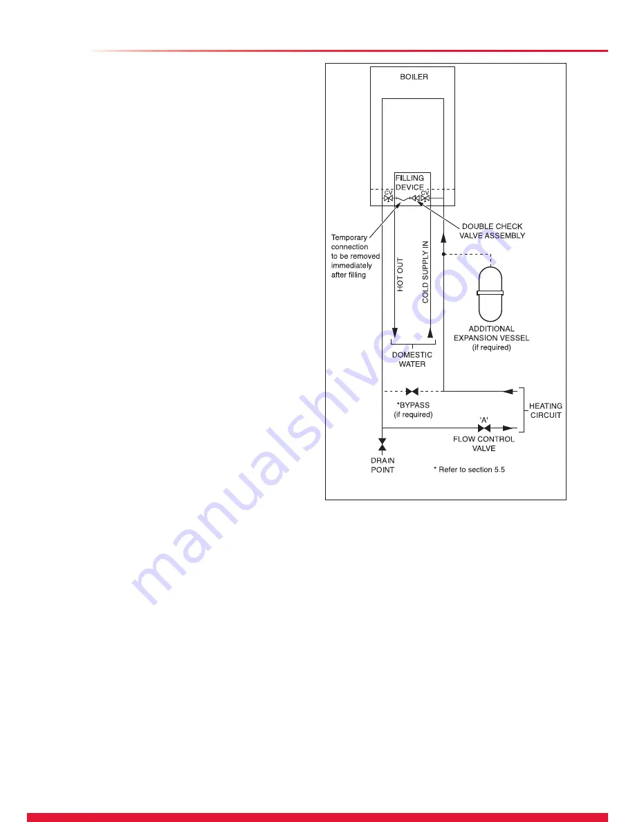
If it is necessary to alter the flow rate, the system can be
fitted with a lockable balancing valve in the main flow or
return pipes shown as valve “A” in diagram 5.1. The flow rate
through the boiler must not be allowed to fall below that given
in section 1 - Specification Table.
5.5 Bypass
The boiler is fitted with an automatic bypass, see diagram 5.2.
Diagram 5.3 shows the pump head remaining for the heating
system depending on the bypass setting and the speed
setting of the pump, see section 12 Commisioning.
Ensure that under no circumstances does the flow rate drop
below the figure specified, refer to section 1 - Specification
Table and section 12.6.
5.6 Filling the Sealed System
The boiler is supplied with a filling device, see diagram 5.4.
This filling device is designed to enable the filling and
pressurisation of the system in the event of loss of pressure.
NOTE:
The water pressure at the boiler must be at least
1.2bar to enable filling the boiler to a minimum pressure. If
not pressurisation must be carried out by an alternative filling
loop.
Suitable external filling systems are shown diagramatically,
see diagram 5.5. The system should be pressurised to 1bar,
indicated on the digital display with no heating demand.
5.7 Draining Points
Draining taps must be provided at all low points of the system,
which will allow the entire system to be drained.
Draining taps shall be to the current issue of BS2879.
Drain points for the appliance are provided at the positions
shown in diagram 5.4.
12800
5.8 Water Treatment
Existing system-
It is ESSENTIAL that prior to installing the
new boiler the system is thoroughly flushed.
New system-
For optimum performance after installation, the
boiler and its associated central heating system should also
be flushed.
Flushing should be carried out in accordance with BS7593:
2006 using a cleanser such as Sentinel X300 or X400, Fernox
Restorer or Salamander corrosion guard cleaner.
IMPORTANT:
Ensure all cleanser is removed from the whole
system before adding an inhibitor.
For long-term corrosion protection, after flushing, an inhibitor
suitable for stainless steel exchangers should be used, refer
to the current issue of BS 5449 and BS 7593 on the use of
inhibitors in central heating systems. Examples are Sentinel
X100 Fernox Protector or Salamander corrosion guard
inhibitor.
Diagram 5.1
Содержание 24cx
Страница 13: ...13 5 Water System Heating Diagram 5 3 13102 Diagram 5 4 13925 13072 Diagram 5 2 ...
Страница 15: ...15 H H Boiler Securing Screw 6 Installation Preparation Diagram 6 1 12778 ...
Страница 20: ...20 9 Safety Discharge Valve and Condensate Connections Diagram 9 2 13000 ...
Страница 22: ...22 14826 Diagram 10 3 15418 10 Telescopic Flue Length Preparation and Installation Diagram 10 2 ...
Страница 26: ...26 Diagram 10 12 13222 15418 10 Standard Flue Length Preparation and Installation Diagram 10 13 ...
Страница 48: ...48 14 Fault Finding 14516 Diagram 14 4 MODE ...
Страница 49: ...49 13012 Diagram 14 5 CENTRAL HEATING DHW 13015 14 Fault Finding ...
Страница 50: ...50 14 Fault Finding 14027 Diagram 14 6 FAULT CODES ...
Страница 63: ...63 18 Declaration of Conformity 14505 ...


