background image


9


S/PDIF:

 This digital audio output is used to connect to AV amplifier “COAXIAL” input. 


For Room 2 only:


RF IN :

This input port is to connect the coaxial cable from your Cable Network provider.


RF OUT: 

This output enables the connection of another receiver.


TV OUT: 

This is used to carry the RF signal to TV set and return back the remote sensor signal 

through "RF & Remote sensor Adaptor Box" via RF cable.


VIDEO OUT: 

This RCA connector is used to connect any external video. 

0-12V 50mA:

 This is used to Connect 12V to an external 0V/12V switch.


AUDIO R/L:

 These RCA connectors are used to connect any external audio amp or system. 

RS 232C:

 This is used to connect your receiver to a computer through a serial cable, for upgrade 

software use.   

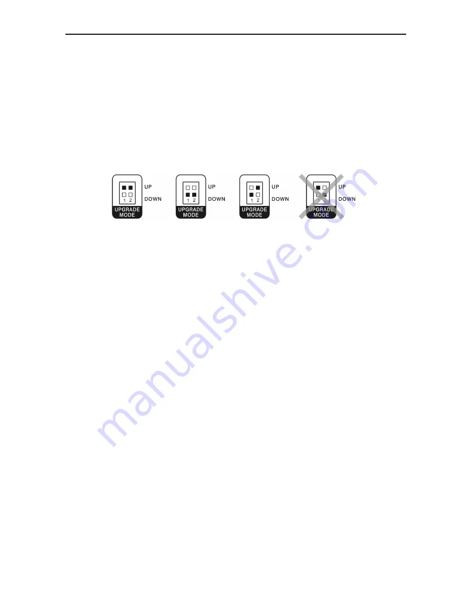
UPGRADE MODE:

 Set up according to below figures. 


Room 1 upgrade 

Room 2 upgrade 

Normal 


Not used 


8. Connecting Your System 

How to connect your STB to various systems 

There are several ways of connecting the STB to your TV, and/or Hi-Fi SYSTEM. Consult your local 
supplier for assistance in setting-up your system that is best suited to your requirements. 


-For Room 1 


Connect STB to a TV set 

Connect your STB to a TV set with SCART, if your TV set is equipped for it. Alternatively you can 
also use RCA connectors. 
 

Connect STB to a Hi-Fi System 

1. Connect Digital optical audio output to your amplifier input. 
2. Connect a RCA stereo cable from the AUDIO L/R jacks, on your STB to the LINE, AUX, SPARE 
or EXTRA input jacks on your Hi-Fi System.   
 

Loop Through 

If you have another STB and you wish to use it, then you can connect it via the loop through. 
Connect one end of the coaxial cable to the Loop Through on the STB and connect the other end to 
the RF IN on your second STB. 
 

-For Room 2 


1. Connect RF cable from RF OUR to Adaptor box, use another RF cable to connect from Adaptor 
box to TV. Connect Remote sensor cable to Adaptpr box. 
2. Connect wireless video transmitter to RCA video and audio out. Connect splitter box to RF OUT 
from Room 2 output, and connect remote rensor jack. Direct sensor of wireless transmitter to sensor 
of Adaptor box. In another room connect wireless video splitter to TV. 

Содержание Digital Cable Receiver DVB-C

Страница 1: ...1 5119 Multiroom Cable ENGLISH Digital Cable Multi room Receiver User s Manual...

Страница 2: ...IONS 13 SERVICES 13 ORGANIZING SERVICES 13 ORGANIZING FAVOURITES 13 11 INSTALLATION 15 CABLE INSTALLATION 15 Manual Installation 15 Auto Installation 15 3 1 1 Blind Scan 15 CA SETTINGS ONLY FOR ROOM 1...

Страница 3: ...UPGRADE BY RS232 21 14 GAME 21 SOKOBAN 22 15 TROUBLE SHOOTING 23 16 SPECIFICATIONS 24 RF SECTION 24 A V MODE 24 MICROPROCESSOR MEMORIES 24 POWER ENVIRONMENT CONDITION 24 PHYSICAL SPECIFICATION 24 CONN...

Страница 4: ...the STB to direct sunlight or do not place it near a heater Do not stack electronic equipments on top of the STB ATTACHMENTS Do not use any attachments that are not recommended as these may cause haza...

Страница 5: ...ent recovery and recycling and thus prevent potential negative effects on the environment and human health which could otherwise arise due to inappropriate waste handling Information on Disposal for B...

Страница 6: ...lay EPG menu MENU Button Display the Main Menu on the screen Return to the previous menu EXIT Button Cancel the user selection and return to the Screen LEFT V RIGHT V Buttons Adjust the volume Increas...

Страница 7: ...ectronic server system of us Moreover we maintain very close working relationships with our customers We take a highly disciplined engineering approach to product design manufacture testing acceptance...

Страница 8: ...infrared signal from remote control unit only for Room 1 ROOM 2 CONTROL POWER Led 2 Lights up while the Room 1 receiver is in standby mode Signal Led 2 When in Room 1 receiving signal is strong the si...

Страница 9: ...Fi SYSTEM Consult your local supplier for assistance in setting up your system that is best suited to your requirements For Room 1 Connect STB to a TV set Connect your STB to a TV set with SCART if y...

Страница 10: ...10 Detail of connecting Diagram 1 By RF cable...

Страница 11: ...11 2 By wireless video transmitter...

Страница 12: ...POWER button to operate the receiver from Standby mode If you did not install it before the Easy Install Menu will be displayed automatically to guide you to install your box Box Setting Language Cho...

Страница 13: ...move the selected service to where you want to locate then all the selected services will be reordered and move to the new location one by one Lock select one or more services and press RIGHT button t...

Страница 14: ...nformation of current service only available in service list MOVE only available for FAV service list select one or more FAV services and press LEFT button to select MOVE icon Press UP DOWN P P button...

Страница 15: ...proper QAM value by using buttons NOTE Every cable network can have different parameters Please ask your cable provider for correct parameters for cable network at your place Auto Installation Auto In...

Страница 16: ...tion about card inserted into card reader module It allows to check all available information about card inserted according to help messages visible on the bottom of the screen NOTE All information sh...

Страница 17: ...atically go to Easy Install menu to re install your system Press MENU EXIT button to abort the operation Set data to factory default data Press OK button to set current database as default data Press...

Страница 18: ...e as the following Receiver Lock The default PIN code is 0000 Censorship Classification Allow Time Control Change Password Time Setting You can set system time sleeping time and wakeup time in this me...

Страница 19: ...t mode for the VCR SCART CVBS only Screen Ratio Set the screen aspect ratio of the TV set connected to this receiver Auto 16 9 Full 4 3 Full 16 9 Letter Box or 4 3 Letter Box TV Standard Set the forma...

Страница 20: ...settings in this menu by using UP DOWN button to select one of the following items and press LEFT RIGHT or OK button to set certain value Details are as the following Banner Display Time OSD Transpar...

Страница 21: ...l for upgrade called AVUpgrade exe and current software or data file dld Continue with ugrade according to Upgrade tool manual WARNING Use only appropriate software dedicated for multi room receiver U...

Страница 22: ...22 Sokoban WARNING All menu functions and operation by remote are the same for Room 1 and Room 2 Except CA Settings which is available only for Room 1...

Страница 23: ...ilable Channel is scrambled Scan channels Ask your local dealer or channel provider about subscryption of the channel Settings you made in the menu have not changed The receiver lost power before bein...

Страница 24: ...s Processor 200 MIPS based CPU RAM 64Mbits FLASH 16Mbits Power Environment Condition Supply Voltage Free Voltage 100 250V AC 50 60Hz Supply Power Max 30W Physical Specification Weight 2 0Kg Dimensions...

Отзывы: