


26
q
16) Using 220 grit sandpaper with a sanding
block, carefully sand the edges of both fairings
smooth.
q
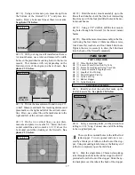
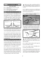
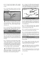
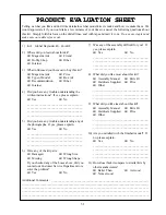
17) One plastic fairing is located on each side
of the fuselage. Position the fairings as shown. See
photo # 52 below.
Photo # 52
If you look closely at the fairings, you will no-
tice they have a long and a short side with a
peak separating the two. Align the peak with the rear
edge of the cowl. The short side should be under-
neath the cowl.
q
18) Glue the fairings to the fuselage sides using
RC256 Canopy Glue. Hold them in place with pieces
masking tape until the glue completely cures.
FINAL ASSEMBLY
INSTALLING THE RECEIVER AND BATTERY
q
1) Plug the servo leads and the switch lead into
the receiver. Plug the battery pack lead into the switch
also. You may want to use two extension leads
plugged into the receiver to make connecting the ai-
leron and retract servo leads easier when you install
the wing.
q
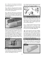
2) Wrap the receiver and battery pack in foam
rubber to protect them from vibration. Position both
of these items behind the servos, cradled in the foam
part of the turtle deck. Use extra foam pieces and scrap
wood glued between the fuselage sides to hold them in
position. Run the extensions forward, under the ser-
vos, to keep them out of the way of the pushrods.
When balancing the airplane you may need to
move the battery or receiver forward or aft to
achieve proper balance. In our test airplane, using a
Magnum XL .46ARNV two stroke engine, the bat-
tery and receiver were mounted as per step # 2.
q
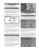
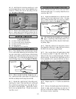
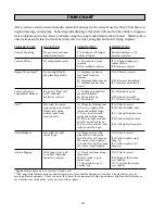
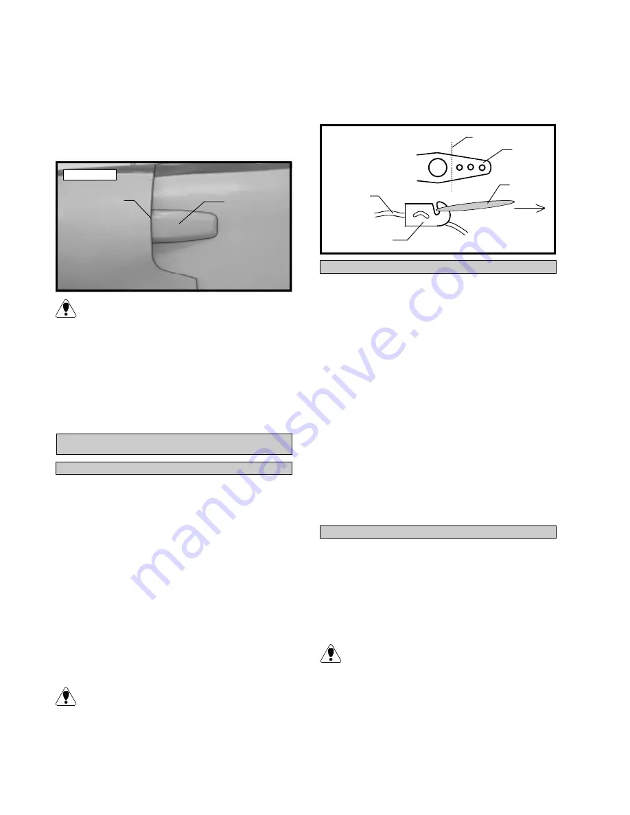
3) Using a 1/16” drill bit, drill a hole through the
side of the fuselage, near the receiver, for the antenna
to exit. Route the antenna out of the fuselage and se-
cure it to the vertical stabilizer using a rubber band and
a modified servo arm. See figure # 23 below.
Fairing
Rear Edge
of Cowl
Figure # 23
q
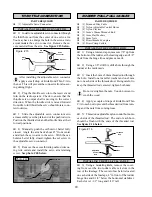
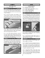
4) The switch should be mounted on the fuse-
lage side, opposite the muffler, close enough to the
receiver so the lead will reach. Use the faceplate of
the switch itself to locate and mark the switch cutout
and mounting holes.
q
5) Cut out the switch hole using a modeling
knife. Use a 5/64” drill bit and drill out the two mount-
ing holes through the fuselage side.
q
6) Secure the switch in place using the two ma-
chine screws provided with the radio system.
q
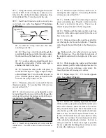
7) Mount the optional Cirrus On-Board Battery
Indicator and the optional Ernst charge jack to the
fuselage side. Plug the battery indicator into an empty
slot in the receiver and secure the charge lead firmly
into the charge jack.
INSTALLING THE SWITCH
Cut
Servo
Arm
Antenna
Modified
Servo Arm
Rubber
Band
To Vertical
Fin
APPLYING THE DECALS
q
8) Using a pair of scissors cut out each decal
along it's edge.
q
9) Using a paper towel soaked with a small
amount of rubbing alcohol, clean the areas of the cov-
ering where the decals will be applied.
For decal placement, use the box cover photos
and the photo on the front of the instruction
manual. Not all of the decals will be used.
q
10) Carefully apply each decal. Use a soft cloth
to rub down the decals and squeeze out any trapped
air beneath them.


