


19
PARTS REQUIRED
q
{1} 1.5mm x 380mm Pushrod Wire
q
{1} 3mm x 270mm Nylon Pushrod Housing
THROTTLE LINKAGE
INSTALLING THE PUSHROD HOUSING
q
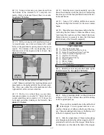
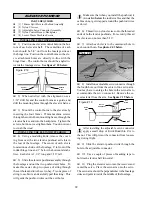
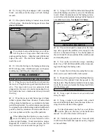
1) Mark and drill a hole through the firewall for
the throttle pushrod housing using a 1/8” drill bit.
Position the hole level with the throttle arm and just
to the outside edge of the motor mounting beam. Be
careful not to drill through the fuel tank!
q
2) Mark and drill a 1/8” hole through the for-
ward bulkhead at the approximate location shown.
See figure # 14 below.
Figure # 14
q
3) Slide the 3mm x 270mm pushrod housing
through the hole in the firewall, through the hole in
the forward bulkhead, and into the servo compart-
ment. Leave about 1/4” of the housing extending
beyond the front of the firewall.
q
4) Apply a couple of drops of Kwik Bond Thin
C/A to the pushrod housing where it exits the fire-
wall and where it passes through the forward bulk-
head. This will secure the housing in place.
q
5) Using a modeling knife, cut off the nylon
pushrod housing 1” in front of the forward servo rail.
q
6) Notice one end of the 1.5mm x 380mm push-
rod wire has a Z-Bend premade in it and the other
end is plain. Slide the plain end of the wire into the
end of the pushrod housing at the firewall. Remove
the throttle arm from the engine and attach the Z-Bend
to the hole farthest out in the throttle arm. Reattach
the throttle arm to the engine.
q
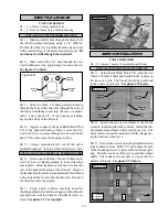
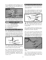
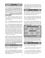
7) Using a pair of pliers, carefully bend the
throttle pushrod wire until it is aligned with the throttle
arm and does not bind when the throttle barrel is ro-
tated. See photo # 37 at top right.
INSTALLING THE THROTTLE PUSHROD WIRE
Photo # 37
q
2) Locate the servos you intend to use for the
elevator, rudder and throttle controls. Install the rub-
ber grommets and brass collets onto the servos. The
brass collets should be installed with the flange fac-
ing the bottom of the servo.
q
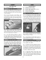
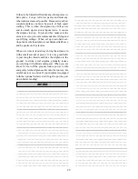
3) Position the servos onto the preinstalled servo
rails as shown below. Drill 1/16” pilot holes for each
of the mounting screws to prevent the rails from split-
ting. Note the locations of the servos and their output
shafts. The rudder servo mounts on top of the two
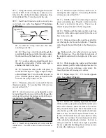
hardwood blocks. See photo # 39 below.
Photo # 38
PARTS REQUIRED
q
{2} 10mm x 10mm x 20mm Hardwood Blocks
SERVO INSTALLATION
INSTALLING THE FUSELAGE SERVOS
q
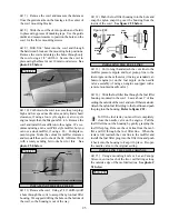
1) Using Kwik Bond Thick C/A, glue the two
10mm x 10mm x 20mm hardwood blocks in place on
the two servo rails. The blocks should be positioned
in the center of each rail. See photo # 38 below.
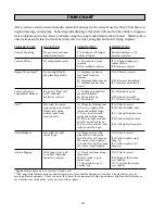
Photo # 39
Pushrod
Wire
Make
Bends
Servo
Rail
Hardwood
Block
Throttle
Pushrod
Pushrod
Housing
Hardwood
Block
Servo
Rail
T
R
E
T = Throttle
R = Rudder
E = Elevator
Front
Forward
Bulkhead
Fuselage
Side
Drill 1/8”
Hole


