background image

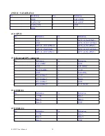
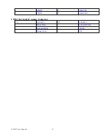
J24: CF card socket

Pin                                      Definition

Pin                                      Definition

1                                          GND

26

GND

2

Data 3

27

Data 11

3

Data 4

28

Data 12

4

Data 5

29

Data 13

5

Data 6

30

Data 14

6

Data 7

31

Data 15

7                                          HDCCS1#

32

HDCCS3#

8                                          GND

33

N/C

9                                          GND

34

IOR#

10                                        GND

35                                        IOW#

11                                        GND

36

+5V

12                                        GND

37                                        Interrupt

13                                        +5V

38                                        +5V

14                                        GND

39                                        CF_CSEL#

15                                        GND

40                                        NC

16                                        GND

41                                        Reset#

17                                        GND

42                                        IOCHRDY

18                                        Disk Address 2

43                                         DMA REQ

19                                        Disk Address 1

44                                         DMA ACK#

20                                        Disk Address 0

45                                        HDD Active#

21                                        Data 0

46                                        DMA66 Dectec

22                                        Data 1

47                                        Data 8

23                                        Data 2

48                                        Data 9

24                                        NC

49                                        Data 10

25                                        GND

50                                        GND

3301520 User s Manual

21

Содержание 3301520

Страница 1: ...User s Manual 3301520...

Страница 2: ...igned to provide reasonable protection against harmful interference when the equipment is operated in a commercial environment This equipment generates uses and can radiate radio frequency energy and...

Страница 3: ...lier to find out how you can ensure that your computer meets safety and regulatory requirements CAUTION Electrostatic discharge ESD can damage NSA components Do the described procedures only at an ESD...

Страница 4: ...1 2 Specifications 6 1 3 Power Consumption Measurement 9 1 4 Board Layout 10 1 5 Board Dimensions 12 Chapter 2Jumper Setting 2 1 Before You Begin 13 2 2 Precautions 13 2 3 Setting Jumpers 14 2 4 Loca...

Страница 5: ...This Page is Left Blank Intentionally 3301520 User s Manual 4...

Страница 6: ...Chapter 1 General Information 3301520 User s Manual 5 Chapter 1...

Страница 7: ...dual channel DDR2 533 667 up to 2 GB Intel PC82573L PCI Express Gigabit Ethernet Controller x 2 supporting two GbE LAN ports PEAK870VL2 Shared integrated graphics controller from chipset with 2048 x 1...

Страница 8: ...chnology Memory BIOS nel Non ECC DDR2 533 667 MHz up to 2 GHz Award System BIOS Plug Play Support Advanced Power Management and Advanced Configuration Power Interface support Chipset Intel 945G Intel...

Страница 9: ...and 4 pin for line out 2 pin power on button switch 2 pin header for SMBus 2 0 Controller 4 pin FAN JST connector x 1 For CPU 3 pin FAN connector x 2 5 pin for key lock power LED HDD Power LED 5 pin...

Страница 10: ...s A Ordering Information 3301520 LF RoHS Compliance PICMG 1 3 Full Size SHB Intel 945G Chipset LGA775 P4 CPU up to 3 8GHz 533 800MHz FSB Dual Core Pentium D support Max 2GB DDR2 400 DIMM VGA integrate...

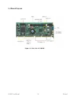
Страница 11: ...1 4 Board Layout Figure 1 2 Overview of 3301520 3301520 User s Manual 10 Chapter 1...

Страница 12: ...1 5 Board Dimensions Figure 1 3 Mechanical Drawing of the 3301520 3301520 User s Manual 11 Chapter 1...

Страница 13: ...Chapter 2 Jumper Setting 3301520 User s Manual 12...

Страница 14: ...tricity can damage many of the electronic components Humid environment tend to have less static electricity than dry environments A grounding strap is warranted whenever danger of static electricity e...

Страница 15: ...you remove the jumper cap or place the jumper cap on just one pin the jumper is OPEN Please see the following illustrations The illustrations on the right show a 2 pin jumper When the jumper cap is p...

Страница 16: ...Select SW1 1 20 2 19 3 18 4 17 5 16 6 15 7 14 8 13 9 12 10 11 RS232 OFF OFF OFF ON OFF ON OFF OFF OFF OFF RS422 OFF ON ON OFF ON OFF ON ON ON ON RS485 ON ON OFF ON ON OFF OFF OFF OFF ON RTC Clear Nor...

Страница 17: ...or J23 Disk on module external power J24 CF card socket JP1 IDE LED Power LED Power ON Reset Buzzer SM Bus System Thermal JP3 IR JP4 Keyboard lock JP5 Line out JP6 Line in JP7 MIC in JP9 82573L LAN1 L...

Страница 18: ...loppy Pin Definition Pin Definition 1 GND 18 DIR 2 DENSEL 19 GND 3 GND 20 STEP 4 NC 21 GND 5 GND 22 Write Data 6 NC 23 GND 7 GND 24 WGATE 8 INDEX 25 GND 9 GND 26 TK00 10 MOTEA 27 GND 11 GND 28 WPT 12...

Страница 19: ...GP21_D_OUT1 PIN21 10 GP27_D_IN3 PIN27 J13 External LPC connector Pin Definition Pin Definition 1 ISA 14 MHZ 9 GND 2 GND 10 LPC DRQ 3 LPC FRAME 11 3 3V 4 GND 12 Series IRQ 5 LPC Address 3 13 3 3V 6 LP...

Страница 20: ...Data 7 23 IOW 4 Data 8 24 GND 5 Data 6 25 IOR 6 Data 9 26 GND 7 Data 5 27 IOCHRDY 8 Data 10 28 GND 9 Data 4 29 DMAACK 10 Data 11 30 GND 11 Data 3 31 Interrupt 12 Data 12 32 NC 13 Data 2 33 DiskAddres...

Страница 21: ...D 9 Parallel Data 7 22 GND 10 Acknowledge 23 GND 11 Busy 24 GND 12 Paper empty 25 GND 13 Select 26 NC J21 External keyboard Pin Definition Pin Definition 1 Keyboard Clock 4 GND 2 Keyboard Data 5 5V 3...

Страница 22: ...32 HDCCS3 8 GND 33 N C 9 GND 34 IOR 10 GND 35 IOW 11 GND 36 5V 12 GND 37 Interrupt 13 5V 38 5V 14 GND 39 CF_CSEL 15 GND 40 NC 16 GND 41 Reset 17 GND 42 IOCHRDY 18 Disk Address 2 43 DMA REQ 19 Disk Add...

Страница 23: ...D 14 Thermal Pin 7 Reset 15 Speaker 8 GND 16 Thermal GND PIN1 IDE LED power LED POWER ON RESET BUZZER SM BUS SYSTEM THERMAL JP3 IR Pin Definition Pin Definition 1 5V 4 GND 2 CIRRX 5 IRTX 3 IRRX JP4 Ke...

Страница 24: ...100 2 Speed1000 JP12 JP14 82573L LAN1 Activity LED 82573L LAN2 Activity LED Pin Definition Pin Definition 1 Activity 2 3 3VSB JP13 JP15 82573L LAN1 LINK100 LED 82573L LAN2 LINK100 LED Pin Definition P...

Страница 25: ...5 MDI2N 11 LINK100 6 MDI1N 12 LINK1000 CON3 Key board mouse Connector Pin Definition Pin Definition 1 Mouse Data 4 Keyboard Clock 2 Keyboard Data 5 5VSB 3 Mouse Clock 6 GND 3301520 User s Manual 24...

Страница 26: ...Chapter 3 Expansion 3301520 User s Manual 25...

Страница 27: ...kets support up to a maximum 2GB DIMM Followings are the recommended memory modules Size MB Technology Type Vendor Remark 512MB DDRII 533 240 PIN non ECC A DATA 2PCS 512MB DDRII 533 240 PIN non ECC UN...

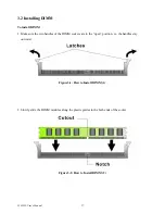
Страница 28: ...ndles of the DIMM sockets are in the open position i e the handles stay outward Figure3 1 How to Install DIMM 1 2 Slowly slide the DIMM modules along the plastic guides in the both ends of the socket...

Страница 29: ...automatically locked the memory modules into the right position of the DIMM socket Figure 3 3 How to Install DIMM 3 4 To take away the memory module just push the both handles outward the memory modul...

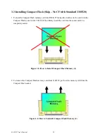
Страница 30: ...h the Compact Flash socket in the 3301520 Then firmly insert the card into the socket until it is completely seated Figure 3 5 How to Install Compact Flash Memory 1 2 To remove the Compact Flash memor...

Страница 31: ...1 1 Opening the Socket a Disengage the Load Lever by pressing down and out on the hook allowing the lever to clear the Retention Tab and rotate to the fully open position b Rotate Load Plate to fully...

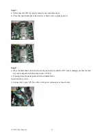
Страница 32: ...tion Step 4 a Place the Heat Sink with Fan Set onto the four holes around the CPU socket making sure that the four screws are aligned with the holes on the 3301520 b Pressing down the metal pads on th...

Страница 33: ...ct with us We will do our best to support you for your products projects and business Global American Inc Address 17 Hampshire Drive Hudson NH 03051 TEL Toll Free U S Only 800 833 8999 603 886 3900 FA...

Отзывы: