


Page 14
1.0 DESIGN
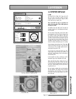
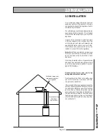
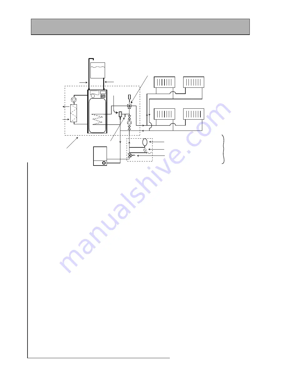
1.3 SYSTEM DETAILS
Remote
F&E
Cistern
BM
A-Class
SP
Boiler
Cold feed
Open Vent
Heating Circuit
Hot Out
Mains Cold In
Components fitted
within appliance case
Expansion Vessel
Pressure Gauge/Filling Loop
Pressure Gauge Relief/Safety Valve
Optional
sealed system
kit
3 port divertor valve
Automatic
bypass valve
Summer use towel
rail blanked connection
Heating System
General
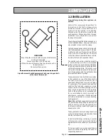
A schematic layout of the heating system in a typical small dwelling is shown
above.
The fl ow and return from the boiler must always run directly to the BoilerMate A-Class
SP and the fl ow should rise continuously to facilitate venting. The heating circuit is
taken from the BoilerMate A-Class and is piped in the conventional manner.
The BoilerMate A-Class SP is only suitable for a sealed heating system and therefore
boiler/heating pipework can run at a higher level than the store.
It is recommended that the F & E cistern for the appliance is fi tted at high level in the
same cupboard as the BoilerMate. However, it can be fi tted remotely up to 6m above
the base of the BoilerMate A-Class i.e. the maximum static pressure in the store must
not exceed 0.6 bar.
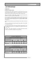
The performance of the system pump and the pressure losses through the SysteMate
2000 primary coil circuit are shown in1.2 Technical Data. The nett pump head available
for the heating circuit can be determined from these fi gures and this nett pump head
should be used for sizing the heating circuit pipework.
For example: At 24 litres/min primary fl ow rate, the pressure loss through the
SysteMate 2000 model SM210 (coil and fi ttings) is 2.1m W.G. (21kPa). The maximum
pump head available at 24 litres/min and setting 3 is 3.2m H
2
O (32kPa), therefore 1.1m
W.G. (11kPa) is available for the boiler circuit.
With sealed heating systems air is released during the fi rst few weeks of operation.
This will need to be vented and the system re-pressurised.
If the automatic model is being used the overfl ow/warning pipe should be installed
in a material suitable for a heating system feed and expansion cistern in accordance
with BS 5449.
An automatic bypass is fi tted on the BoilerMate
A-Class SP to compensate for pressure (i.e. fl ow)
rate changes in the heating circuit e.g. when the
thermostatic radiator valves close. The system
does not require any other bypass valves but
a bypass radiator used in conjunction with a
room thermostat can be used if required to
provide a boiler interlock. The bypass valve
must be set by the installer to suit the system
ie to provide minimum fl ow required for the
boiler when all TRV’s are closed.
There shall be no permanent connection to
the mains water supply for fi lling the system,
even through a non-return valve without
the approval of the Local Water Authority.
An approved filling loop is required with
the BoilerMate A-Class (available as part of
an optional extra kit) which this should be
disconnected after commissioning the system.
This should be located adjacent to the boiler
along with a suitable expansion vessel gauge
and pressure relief valve (also available as part
of the optional extra kit) as shown above.
Содержание BMA 120 SP
Страница 44: ...Page 44 ...
Страница 45: ...Page 45 BOILERMATE A CLASS SP ...


