27
Model
MCB - C Type
MCB - D Type
16A
20A
25A
16A
20A
25A
100LED
1
2
2
1
2
3
80LED
1
2
2
1
2
3
64LED
1
2
2
2
3
4
15LED
2
2
2
2
3
4
20LED
1
2
2
1
2
3
256LED
3
3
4
3
4
4
320LED
1
2
2
1
2
3
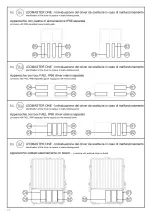
di alimentazione vale quanto detto al punto
4.2 per cavo bi terra separata. Per il
collegamento del cavo DMX l’apparecchio viene
fornito con connettori maschio “W” (connettore
maschio_OUT) e femmina “K” (connettore
femmina_IN) tipo XLR già montati ed in uscita
dall’apparecchio; altri due connettori maschio e
femmina tipo XLR vengono forniti in un sacchetto.
Per il collegamento alla linea DMX occorre
montare i connettori presenti nel sacchetto sui
cavi di collegamento (non forniti da FAEL) tra
gli apparecchi eseguendo una saldatura come
in
figura 37
. Per la protezione dei cavi DMX è
opportuno inserire tali cavi in apposite tubazioni
di protezione separate dal cavo di potenza.
Utilizzare un cavo DMX ad impedenza costante
a 2 poli interni schermati, specifico per la
connessione di apparecchiature che utilizzano il
protocollo DMX512 con impedenza nominale di
120 Ohm. Scegliere un cavo con guaina esterna
consona alle temperature ambientali della zona
di installazione.
Parte comune per tutti i capitoli sopra
In base al pressacavo utilizzato (G1, G2 e/o G3):
verificare il serraggio, con chiave inglese, del
corpo “X” (vedere
figura
11
) del/i pressacavo/i
applicando un momento torcente di 4Nm;
serrare con cura e a fondo, con chiave inglese, la
ghiera “Y” (vedere
figura
11
) del/i pressacavo/i
applicando un momento torcente di 3.5Nm. Una
volta collegato elettricamente l’apparecchio,
richiudere il vano accessori elettrici serrando
le 3 viti V” (vedere
figure 3a - 3b
) in acciaio
inox applicando un momento torcente di
5.2Nm assicurandosi che la guarnizione sia
perfettamente nella sua sede: all’inizio chiudere
parzialmente le 3 viti “V” in acciaio inox ed
infine serrarle definitivamente. Verificare che il
coperchio sia perfettamente in battuta sul vano
accessori elettrici.
Numero massimo di apparecchi comandabili
da ciascun interruttore magnetotermico.
Soluzione valida per tutte le versioni sopra
riportate:
È consigliabile, per ogni proiettore, utilizzare
un interruttore bipolare da 16 Ampere con
caratteristiche di intervento di tipo C o D (è
preferibile il tipo MCB – D). Non superare il
numero massimo di apparecchi per interruttore
(vedere tabella sopra). Eventuali teleruttori
devono essere sovradimensionati e di tipo
gravoso. Eventuali differenziali devono essere
con I∆ ≥ 0,3÷0,5mA, ritardati di tipo S. Per
interruttori tripolari e quadripolari (è preferibile
il tipo MCB – D) moltiplicare per 3 il numero
di proiettori indicati in tabella; ovviamente i
proiettori devono essere distribuiti su tutte le
fasi in modo equilibrato.
Per l’alimentazione di potenza del proiettore
vedere il:
•
collegamento linea-proiettore
Per versione LEDMASTER ONE asimmetrico con
cablaggio interno o con cablaggio esterno on
board (vedere
figura 21
).
•
collegamento linea-gruppo di
cablaggio-proiettore
Per versione LEDMASTER ONE asimmetrico con
cablaggio separato (vedere
figura 22
).
USO E MANUTENZIONE
Manutenzione ordinaria
• Pulizia del vetro da eseguire una volta l’anno.
• Pulizia generale del proiettore da eseguire una
volta l’anno.
• Per piastre armadio: verificare spia dell’SPD
the three-pole cable provided in the paragraph
4.1 to connect the power cable. Follow the
indications related to the two-pole cable +
separated ground provided in the paragraph
4.2 to connect the power cable. The appliance
features XLR type male “W” (male connector_
OUT) and female “K” (female connector_IN)
connectors already mounted, available at the
appliance output, meant for the connection
of the DMX cable; other two XLR type male
and female connectors are supplied in a bag.
For the connection to the DMX line, fit on the
connection cables (not supplied by FAEL),
between appliances, the connectors supplied
in the bag and seal as shown in
figure 37
. To
protect the DMX cables it is recommended to
have them inserted in special protection pipes
separated from the power cable. Use a 2 inner
shielded poles DMX cable having constant
impedance specific for the connection of the
appliances that require DMX512 protocol with
120 Ohms nominal impedance. Use a cable
with outer sheath suitable to the environmental
temperatures of the installation area.
Part shared by all previous chapters
Depending on the cable gland used (G1, G2 and/
or G3): using a spanner, apply a torque 4Nm to
check the tightening of the housing “X” (check
the
figure
11
); use a spanner and apply a torque
of 3.5Nm to tighten carefully and completely
the ring nut “Y” (check the
figure
11
). Once the
appliance is connected, close back the electrical
accessories compartment and tighten the 3 “V”
stainless steel screws (check
figures
3a
-
3b
) by
applying 5.2Nm torque, making sure the gasket
is perfectly fit: tighten first partially the 3 “V”
stainless steel screws, then tighten completely.
Ensure the cover is perfectly abutted to the
electrical accessories compartment.
Maximum number of projectors that can be
controlled by each circuit breaker.
This solution applies to all versions listed above:
È it is recommended to use for each projector
a two-pole 16 amps switch with C or D type
tripping characteristics (preferably the MCB - D
type).
Do not exceed the maximum number of
appliances per switch (check the table above).
All contactors must be oversized and heavy-duty
type.
The differential circuit breakers must of the
delayed type, with ∆ ≥ 0.3÷0.5 mA.
For 3-pole and 4-pole switches (preferably of
the MCB - D type), multiply by 3 the number
of projectors indicated in table; obviously, the
projectors must be evenly distributed on all
phases.
For the power supply of the projector check:
• the line-projector connection
Asymmetric version LEDMASTER ONE with
internal wiring or with built-in external wiring
(check the
figure
21
).
• the line-wiring unit-projector connection
Asymmetric version LEDMASTER ONE with
separated wiring (check
figure
22
).
USE AND MAINTENANCE
Routine maintenance
• Clean the glass once a year.
• Perform the general cleaning of the projector
once a year.
• Cabinet plates: check the SPD indicator in
alternating current at the plate input and replace
if the light is red.
le câble DMX, l’appareil est fourni avec des
connecteurs mâle “W” (connecteur mâle_OUT)
et femelle “K” (connecteur femelle_IN) type
XLR déjà montés à la sortie de l’appareil; deux
autres connecteurs, mâle et femelle de type
XLR sont fournis à part, dans un sachet. Pour le
branchement à la ligne DMX, il faut monter les
connecteurs présents dans le sachet des câbles
de branchement (non fournis par FAEL) entre
les appareils et les souder, comme l’indique
la
figure
37
. Pour protéger les câbles DMX, il
convient de les insérer dans des tuyauteries
de protection séparées du câble de puissance.
Utiliser un câble DMX à impédance constante
à 2 pôles internes blindés, spécifique pour
connecter les appareillages utilisant le protocole
DMX512 avec impédance nominale de 120
Ohm. Choisir un câble muni de gaine externe
adaptée aux températures ambiantes de la zone
d’installation.
Partie commune à tous les chapitres ci-
dessus
Selon le presse-câbles utilisé (G1, G2 et/
ou G3): Vérifier le serrage du corps “X” (voir
figure
11
) du/des serre-câbles avec une clé anglaise,
en appliquant un moment de torsion de 4Nm.
Toujours avec la clé anglaise, serrer bien à fond
le collier de serrage “Y” (voir
figure
11
) du/
des serre-câbles en appliquant un moment de
torsion de 3.5Nm. Après avoir branché l’appareil
électriquement, refermer le compartiment des
accessoires électriques en serrant les 3 vis V”
en acier inox (voir
figures 3a - 3b
) en appliquant
un moment de torsion de 5.2Nm et en contrôlant
que la garniture est parfaitement logée dans son
emplacement: au début, ne fermer les 3 vis “V”
que partiellement puis les serrer définitivement.
Vérifier que le couvercle est parfaitement en
butée sur le compartiment des accessoires
électriques.
Nombre maximum d’appareils pouvant être
commandés depuis chaque interrupteur
magnétothermique.
Solution valable pour toutes les versions
reportées ci-dessus:
On conseille, pour chaque projecteur, d’utiliser
un interrupteur bipolaire de 16 Ampères avec
des caractéristiques d’intervention de type C
ou D (le type MCB – D est à préférer). Ne pas
dépasser le nombre maximum d’appareils
par interrupteur (voir tableau ci-dessus). Tout
éventuel télérupteur doit être surdimensionné et
de type lourd. Tout éventuel différentiel doit être
avec I∆ ≥ 0,3÷0,5mA, retardés de type S. Pour
interrupteurs tripolaires et quadripolaires (le
type MCB – D est préférable) multiplier par 3 le
nombre de projecteurs indiqués en tableau; les
projecteurs doivent être évidemment distribués
sur toutes les phases de façon équilibrée.
Pour l’alimentation de puissance du projecteur,
voir le:
•
branchement ligne-projecteur
Pour version LEDMASTER ONE asymétrique
avec câblage interne ou avec câblage externe
on board (voir
figure
21
).
•
branchement ligne-groupe de
câblage-projecteur
Pour version LEDMASTER ONE asymétrique avec
câblage séparé (voir
figure
22
).
UTILISATION ET ENTRETIEN
Entretien courant
• Nettoyage du verre à effectuer une fois par an.
• Nettoyage général du projecteur effectuer
une fois par an.
• Pour les plaques de l’armoire: vérifier le
témoin de l’SPD en courant alterné à l’entrée de
DMX wird das Gerät mit Steckern „W“ (Stecker_
OUT) und Buchse “K“ (Buchse_IN) vom Typ XLR
bereits montiert und am Ausgang des Gerätes
geliefert; Zwei weitere Stecker und Buchsen
vom Typ XLR werden in einem Beutel geliefert.
Um eine Verbindung mit der DMX-Leitung
herzustellen, müssen die Verbinder im Beutel an
den Verbindungskabeln (nicht von FAEL geliefert)
zwischen den Geräten durch Schweißen
angebracht werden, wie in
Abbildung
37
gezeigt. Zum Schutz von DMX-Kabeln empfiehlt
es sich, diese Kabel in vom Stromkabel
getrennten Schutzrohren zu verlegen.
Verwenden Sie ein DMX-Kabel mit konstanter
Impedanz mit 2 abgeschirmten internen Polen,
speziell für den Anschluss von Geräten mit dem
DMX512-Protokoll mit einer Nennimpedanz
von 120 Ohm. Wählen Sie ein Kabel mit einem
Außenmantel, der den Umgebungstemperaturen
des Installationsbereichs entspricht.
Gemeinsamer Teil für alle oben
aufgeführten Kapitel
Basierend auf der
verwendeten Kabeldurchführung (G1, G2
und/oder G3): Überprüfen Sie, mit einem
Drehmomentschlüssel, den Anzug des Gehäuses
“X“ (siehe Abbildung 11) der Kabeldurchführung/
en mit einem Drehmoment von 4Nm. Ziehen
Sie die Schraube “Y” (siehe
Abbildung 11
)
der Kabeldurchführung/en mit Drehmoment
3.5Nm vorsichtig an. Wenn das Gerät elektrisch
angeschlossen ist, das elektrische Zubehörfach
wieder schließen indem die 3 Schrauben “V“
(siehe
Abbildungen
3a - 3b
)aus Edelstahl mit
einem Drehmoment von 5.2Nm angezogen
werden, um sicherzustellen, dass die Dichtung
perfekt sitzt. Zu Beginn die 3 Schrauben “V“ aus
Edelstahl teilweise anziehen und abschließend
fest anziehen. Stellen Sie sicher, dass die
Abdeckung perfekt am elektrischen Zubehörfach
anliegt.
Maximale Anzahl von Geräten, die von jedem
magnetothermischen Schalter gesteuert
werden können.
Lösung gültig für alle oben aufgeführten
Versionen:
Es wird empfohlen, für jeden Scheinwerfer
einen zweipoligen Schalter mit 16 Ampere mit
Eingriffseigenschaften vom Typ C oder D zu
verwenden (der Typ MCB - D ist vorzuziehen).
Die maximale Anzahl von Geräten pro Schalter
nicht überschreiten (siehe Tabelle oben). Alle
Fernschalter müssen überdimensioniert und
schwer sein. Alle Differentialschalter müssen
mit I∆ ≥ 0,3 ÷ 0,5mA, verzögerte Art S sein. Bei
dreipoligen und vierpoligen Leistungsschaltern
(Typ MCB-D ist vorzuziehen) die Anzahl der in
der Tabelle angegebenen Scheinwerfer mit
3 multiplizieren; die Scheinwerfer müssen
natürlich in allen Phasen ausgewogen verteilt
sein. Zur Stromversorgung des Scheinwerfers
siehe:
• Anschluss Linie-Scheinwerfer
Für die asymmetrische Version LEDMASTER
ONE mit interner Verkabelung oder externer
Verkabelung On-Board (siehe
Abbildung 21
).
•
Anschluss Linie-Verkabelungseinheit-
Scheinwerfer
Für die asymmetrische Version LEDMASTER ONE
mit getrennter Verkabelung (siehe
Abbildung
22
).
BEDIENUNG UND WARTUNG
Gewöhnliche Wartung
• Reinigung des Glases einmal pro Jahr.
• Allgemeine Reinigung des Scheinwerfers
einmal pro Jahr.
• Für Schrankplatten: Prüfen Sie die
SPD-Kontrolllampe im Wechselstrom am
30
Содержание 514084500
Страница 1: ...Glamox O92 O93 ASY User manual ...
Страница 6: ...3 3 6 ...
Страница 7: ...4 7 ...
Страница 8: ...5 5 8 ...
Страница 14: ...11 14 ...
Страница 16: ...13 13 16 ...
Страница 17: ...14 17 ...
Страница 18: ...15 18 ...
Страница 20: ...17 20 ...
Страница 22: ...19 22 ...
Страница 24: ...21 24 ...
Страница 26: ...23 26 ...
Страница 28: ...25 28 ...
Страница 31: ...28 31 ...
Страница 32: ...29 32 ...
Страница 33: ...30 33 ...
Страница 35: ...32 35 ...
Страница 36: ...33 36 ...
Страница 38: ...35 Note 38 ...
Страница 39: ...39 ...


