background image

5

2

3

1

2

3

CAT 2

N/O

N/C

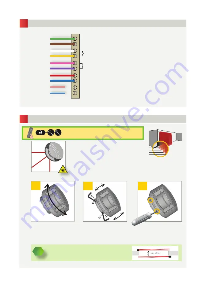
Adjust the 

lateral position

 of 

the detection field.

Adjust the 

tilt angle

 of the 

detection field with the hex 

key.

Lock the position

 of the 

mounting bracket to avoid 

malfunctioning in case of 

extreme vibrations.

Unlock the sensor and activate the 

visible laser beams.

(Both primary and secondary power cables 
must be wired into the power supply)

WIRING

POSITIONING

POWER
POWER SUPPLY  -

POWER
POWER SUPPLY  -

RELAY 1 - OPTIONAL FIELD

RELAY 2 - SAFETY FIELD

NOT USED

GREEN

BROWN

WHITE

YELLOW

PINK

VIOLET

RED

BLUE

WHITE/RED

WHITE/BLUE

CAUTION!


The distance between the inner curtains of the 2 sensors 

must be max. 20 cm.

C1
C2
C3
C4

PRIMARY

(Recommended Power Supply 24 VDC - 
GJD’s ALT-100-24 )

SECONDARY

The visible laser beams indicate approximately 
the postion of curtain C1 and limit the angle of 
the detection field.

The visible laser beams stay activated for 15 

minutes or can be turned off the same way they 

were activated.

Содержание D-TECT GJD505

Страница 1: ...1 GJD D TECT Laser User Manual GJD509 max detection range of 10m x 10m GJD505 max detection range of 5 0m x 5 0m LASER SCANNERS FOR BUILDING AUTOMATION AND SECURITY...

Страница 2: ...s responsible for carrying out a risk assessment and installing the sensor and the door system in compliance with applicable national and international regulations and standards on door safety and if...

Страница 3: ...laser sweep reception 3 LED signal 4 4 screw for position lock 2 5 connector 6 protection cover 7 visible laser beam 3 8 notch for tilt angle adjustment 2 9 adjustable bracket 10 cable conduit 4 1 De...

Страница 4: ...ning If drilling an opening is not possible use the cable conduits on the back side of the bracket Position the bracket and fasten the 4 screws firmly in order to avoid vibrations Close the protection...

Страница 5: ...G POSITIONING POWER SUPPLY POWER SUPPLY POWER SUPPLY POWER SUPPLY RELAY 1 OPTIONAL FIELD RELAY 2 SAFETY FIELD NOT USED GREEN BROWN WHITE YELLOW PINK VIOLET RED BLUE WHITE RED WHITE BLUE CAUTION The di...

Страница 6: ...m 5 0 m no field no field The detection field should be free of snow buildups heavy rain snowfall fog or other moving objects Stay outside of the detection field to avoid disturbances Select the corr...

Страница 7: ...proximately 10 cm for every meter mounting height Example at 5 m the distance is 50 cm indoor outdoor low outdoor med outdoor high OUTPUT ACTIVATION DELAY approximate values off EX C1 C2 active on opt...

Страница 8: ...h time the sensor position is changed or new objects are added to or changed in the detection zone ATTENTION This PB teach in is different from the safety field teach in When the red LED flashes very...

Страница 9: ...VALUES SAVING AN ACCESS CODE DELETING AN ACCESS CODE The access code is recommended for sensors installed close to each other After unlocking the red LED flashes and the sensor can be adjusted by rem...

Страница 10: ...and BLUE cable have to be connected to the test input or the power supply Check the size of the fields Launch a teach in Step out of the field and or remove the any object s from the field Activate th...

Страница 11: ...D TECT Laser 505 2 1 cm 3 m 3 5 cm 5 m 700 mm x 300 mm x 200 mm testbody A according to EN 12445 wavelength 905 nm max output pulse power 75 W CLASS 1 wavelength 650 nm max output CW power 3 mW CLASS...

Страница 12: ...12 Unit 2 Birch Business Park Whittle Lane Heywood Greater Manchester OL10 2SX www gjd co uk info gjd co uk 44 0 1706 363 998 ENGINEER NOTES...

Отзывы: