background image

USER MANUAL


DIGITAL READOUT  VISION 518


MT02_A31_B_VI518_GIVI_ENG      rev. A


Pag. 22/32


With this function it is possible to set the duration of the intervention of two relays at the 
programmed positions (see function F 42). 
Let us suppose that, in their rest condition, relay 1 has been set with the NC status 
(normally closed) and relay 2 has been set with NO status (normally open). In addition, let 
us suppose the operator wants to program the following intervention positions: 


  RELAY 

R1 

IN THE POSITION 150.00  

FOR   0.5 sec. 

  RELAY 

R2 

IN THE POSITION 300.00  

FOR   2.0 sec. 


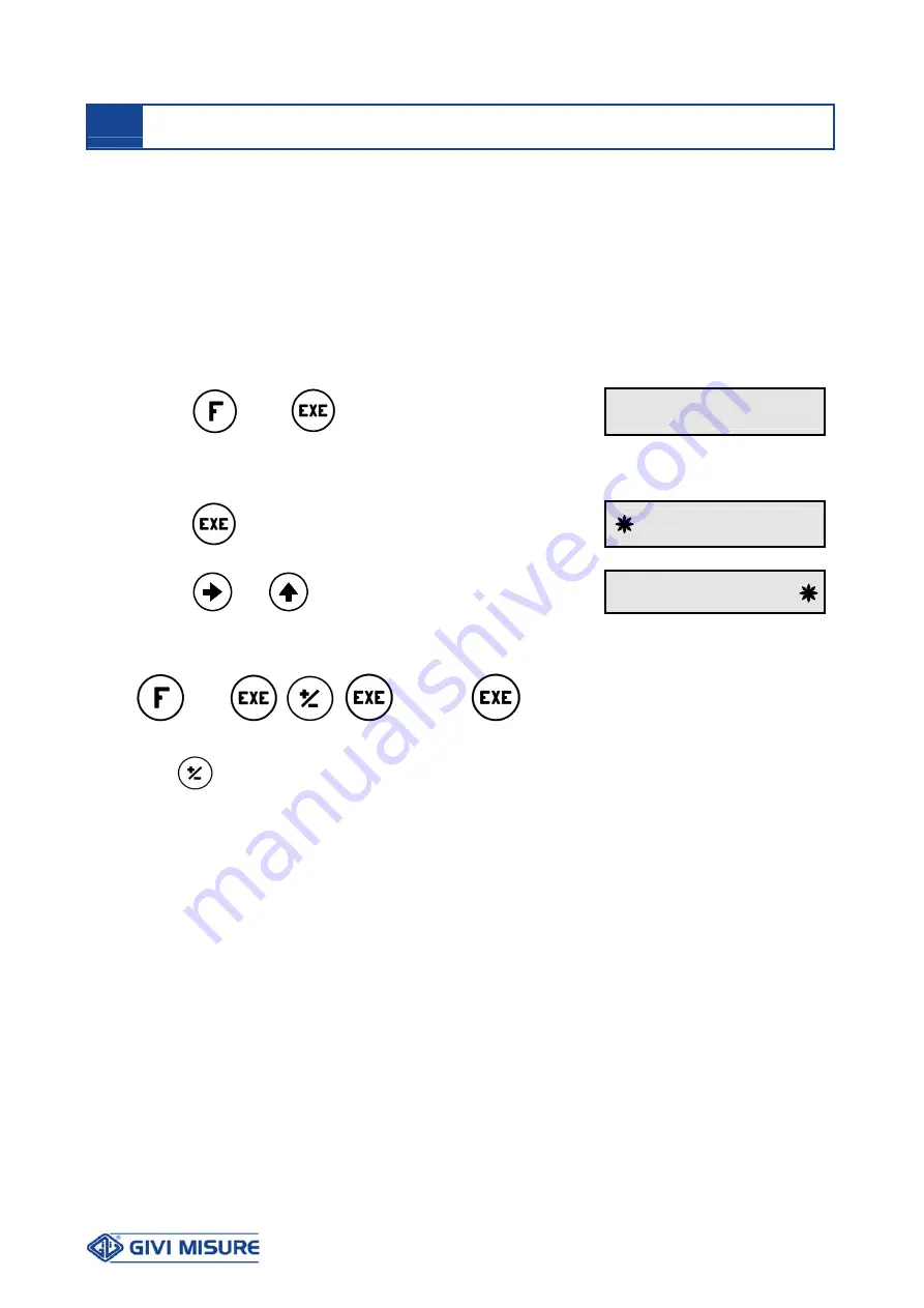
Press


4 1

r E L E          1

 
To set a time of 0.5 sec for relay 1, 
 

Press

enter the desired duration for the relay 
intervention


X


X


X


X


X


.


X


X


Use 

 and


to enter it and press EXE 

0


0


0


0


0


0


.


5


To set a time of 2 sec for relay 2, 


press


4 1


2 . 0 0


Note.

 The


key is used to select the desired relay (2 in our example). 

 
The program has been completed and, in our example, the two relays act like measuring 
length limits. In fact, relay 1 closes its contact for 0.5 seconds if the position passes from a 
value higher than 150.00 to a lower value; relay 2, instead, closes its contact for 2 seconds 
if the position passes from a value lower than 300.00 to a higher value. 

 
Important: 

Timed relay outputs work with the relay outputs in NO status (normally open) 

in their rest condition. They close their contact for the programmed duration of the 
intervention. 
With function F 40, it is possible to program the relays status (NO or NC) in their rest 
condition. Based on this programming, the generation of the intervention impulse will occur 
as indicated below. 
 

 SETTING TIMED RELAY OUTPUTS 

F 41 

Содержание VISION 518

Страница 1: ...User Manual Digital Readout V VI IS SI IO ON N 5 51 18 8 www givimisure it...

Страница 2: ...ON F 11 p 13 MIDPOINT CALCULATION F 15 p 13 INVERSION OF COUNTING DIRECTION F 22 p 14 LOAD POSITION PRESET F 23 p 14 DISABLING THE AUTOMATIC REF SEARCH F 24 p 15 COUNTING MODE F 25 p 16 LINEAR CORRECT...

Страница 3: ...ith a number of specific functions for any type of machine tool PRELIMINARY REMARKS Disposal of waste electrical and electronic equipment WEEE European Council Directive 2002 96 EC The use of the WEEE...

Страница 4: ...trument is connected must be equipped with a sectioning device in compliance with the regulations in force positioned close to the instrument PREVENTION To avoid fires or explosions the instrument sho...

Страница 5: ...USER MANUAL DIGITAL READOUT VISION 518 MT02_A31_B_VI518_GIVI_ENG rev A Pag 5 32 DIMENSIONAL SPECIFICATIONS DRILLING TEMPLATE 92 x 45 mm 140 96 48 10 48 96 10 140 48...

Страница 6: ...1 Relay 1 common contact NA1 N O Relay 1 contact C2 Relay 2 common contact NA2 N O Relay 2 contact V Encoder power supply output 12 V 05 V 0 V 0 V Encoder power supply LOAD Load position input connect...

Страница 7: ...ides a series of visual signals to support the user during configuration and use When pressing a key messages appear on the display according to the operation function see this manual Finally the inst...

Страница 8: ...ot consider shifts of the carriage made whenever the mains power supply is disconnected due to inertia manual maneuvers or thermal expansion Whenever any of the above occurs the position shown in the...

Страница 9: ...rruption of power supply voluntary or not occurs the instrument proposes to the operator the zero reference REF search to avoid the displaying of incorrect positions LAST POSITION This is the case for...

Страница 10: ...the axis has terminated the zero reference REF search displaying an error message at the pressure of any key except CLR The operator can then decide to A Complete the zero reference search B Cancel i...

Страница 11: ...d only affects the counter of the selected counting system For instance it is possible to reset the ABS counter in a given point ORIGIN and operate in INCREMENTAL counting that is handier and more ver...

Страница 12: ...al point therefore from 999999 9 to 999999 9 for 100 m resolution from 99999 99 to 99999 99 for 10 m resolution from 9999 999 to 9999 999 for 1 m resolution The F 00 function can be used to delete the...

Страница 13: ...he carriage along the axis Let us suppose that in that position the axis display will show the value 30 00 which is not necessary to reset Press 1 5 3 0 0 0 Note The decimal point of the position will...

Страница 14: ...the operator that the inversion of direction has been executed Press because the axis has to be inverted d i r Press the selection is confirmed and the axis is inverted X X X X X X X X After having c...

Страница 15: ...e described below Press the first digit will flash X X X X X X X Press and the value will be set preset 5 0 0 0 It is possible to recall the load position also with an external contact connected to th...

Страница 16: ...The counting mode can be direct double quadruple or mono directional Press 2 5 C n t n 1 The display will show the direct counting mode n1 Press to select the double counting mode n2 C n t n 2 Press t...

Страница 17: ...performed moving the axis by 400 00 mm value shown on the display but an error has been detected positive or negative For instance the measured piece is either longer or shorter than intended That me...

Страница 18: ...irm the selection After having confirmed with the EXE key the display will be enabled for counting While choosing the reading mode consider that A RADIAL READING the display shows the same value of th...

Страница 19: ...d resolution r 0 0 Press to confirm the selection 1 At any pressure of the key the decimal point shifts to the lower resolution 2 The variable resolution set will be maintained also after turning off...

Страница 20: ...olution is 3 6 seconds of an arc 0 001 that can be obtained with an encoder having 90 000 PPR If the instrument has been configured by the Manufacturer in angular reading the operator can select the r...

Страница 21: ...ted only if the instrument has been required with this option Vice versa the operator should contact the Manufacturer To activate the function Press 4 0 r E L E no Press to modify the setting r E L E...

Страница 22: ...it and press EXE 0 0 0 0 0 0 5 To set a time of 2 sec for relay 2 press 4 1 2 0 0 Note The key is used to select the desired relay 2 in our example The program has been completed and in our example th...

Страница 23: ...tation direction To disable the timed output and return to the standard relay output it is sufficient to set a timing duration of 0 seconds on the concerned relay Axis in linear reading Let us suppose...

Страница 24: ...relays activate according to the formula intervention angle circular sector Let us suppose that the operator wants to activate the relay 1 at the position of 90 with a circular sector having an angle...

Страница 25: ...is in linear reading NC NC NO normally open dt NO NC normally closed NO NO Example 1 Relay 1 NO at the position 100 Relay 2 NC at the position 100 RELAY 2 RELAY 1 100 100 0 Example 2 Relay 1 NO at the...

Страница 26: ...ng with the axis in angular reading NC NC NO normally open dt NO NC normally closed NO NO Example 1 Relay 1 NO at the angle 90 with a sector angle of 2 91 90 89 Example 2 Relay 1 NC at the angle 90 wi...

Страница 27: ...8 9 n c RX TX n c 0 V n c n c n c n c The SLAVE needs to have the same parameters If the digital readout has the serial output each pressure of the key will start the transmission Data have the follo...

Страница 28: ...on of displayed positions on the serial output Press 5 5 S E n d no Press to select S E n d yes Press to confirm the selection Data on ABS or INC positions are sent every 0 4 sec in ASCII mode and hav...

Страница 29: ...call a function that cannot be selected with the key Press to enter the function selection F F n Press F 0 0 0 0 Use and to enter the number of the desired function and press EXE F 9 8 7 7 1 Press to...

Страница 30: ...24 Vac Memory permanent for configuration and user settings last data operating memory Linear resolution 200 100 50 20 10 5 2 1 0 5 m 0 01 0 005 0 002 0 001 0 0005 0 0002 0 0001 0 00005 0 00002 inch...

Страница 31: ...lacement of those parts that have been damaged by negligence or misuse improper installation or maintenance maintenance performed by unauthorized personnel transport or any other circumstance that exc...

Страница 32: ...IGHE OTTICHE OPTICAL SCALES SISTEMI MAGNETICI MAGNETIC SYSTEMS ENCODER ROTATIVI ROTARY ENCODERS VISUALIZZATORI DIGITAL READOUTS POSIZIONATORI POSITION CONTROLLERS GIVI MISURE S r l A SOCIO UNICO Via A...

Отзывы: