background image

Software Installation Process

21

Chapter 4

Software Installation Porcess

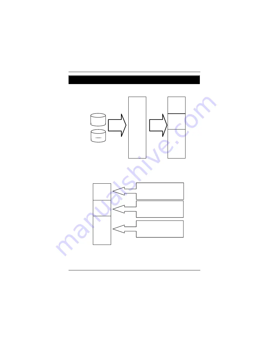
4-1: System Partition Layout

DISK

DISK


RAID

Logical
Volume


System

Recovery

6000

MB

6000

MB

Un-

allocated

6000

MB

6000

MB

Un-

allocated


C:
Primary OS Partition
For Normal Boot


D:
Faiover OS Partition
For Emergency Boot


Unallocated
Data Partition
For User Data

Содержание GS-ST000

Страница 1: ...System Installation Guide GS ST000 Rev 1 0 25A08 0ST00 F00 Storage Server ...

Страница 2: ... 2 5 PCI Expansion Card Installation 14 2 6 Hard Disk Drive Installation 15 2 7 CD ROM Drive Installation 16 Chapter 3 Appearance of GS ST000 18 3 1 Front View of GS ST000 18 3 2 Rear View of GS ST000 19 3 3 Front Panel LEDs Definition 20 3 4 Rear LEDs Definition 20 Chapter 4 Software Installation Porcess 21 4 1 System Partition Layout 21 4 2 Before Recovery 22 4 3 System Recovery Procedure 23 4 4...

Страница 3: ...setting 37 6 4 1 Entering Password 37 6 4 2 Setting Password 38 6 5 Return to the Main Menu 39 6 6 Configure LAN IP Address Netmask Gateway and DNS 39 6 7 Welcome Message Setting 41 6 8 Display Time Setting 42 6 9 Computer Information Menu Setting 43 6 10 System Time Setting 44 6 11 Rebooting System Rebooting 45 6 12 Powering Down 46 Appendix 47 Connector Icon Description 47 System Maintenance Dia...

Страница 4: ...and product usage instructions Do not use this product near water or a heat source Set up the product on a stable work surface or so as to ensure stability of the system Openings in thecaseare provided forventilation Do notblock or coverthese openings Makesure you provide adequatespace around thesystem for ventilationwhen you set upyour work area Never insert objects of any kind into the ventilati...

Страница 5: ...s own expense Properly shielded and grounded cables and connectors must be used in order to meet FCC emission limits Neither the provider nor the manufacturer are responsible for any radio or television interference caused by using other than recommended cables and connectors or by unauthorized changes or modifications to this equipment Unauthorized changes or modifications could voidthe user s au...

Страница 6: ...entifies certified equipment This certification means that the equipment meets certain telecommunications network protective operational and safety requirements The Department does not guarantee the equipment will operate to the user satisfaction Before installing this equipment users ensure that it is permissible to be connected to the facilities of the local Telecommunications Company The equipm...

Страница 7: ...e termination on a loop may consist of any combination of devices subject only to the requirement that the sum of the Load Numbers of all the devices does not exceed 100 for European users only CAUTION v Danger of explosion if battery is incorrectly replaced v Replace only with the same or equivalent type recommended by the manufacturer v Dispose of used batteries according to the manufacturer s i...

Страница 8: ...Welcome to the Gigabyte GS ST000 Entry Storage Server System Installation Guide The guide book provides instructions for configuration of GS ST000 This installation guidewill assiste you in installingall the essential components forthesever system For your protection pleaseread and undertand all of the safety and operatinginstructions regarding your GigabyteServerand retainfor futurereference The ...

Страница 9: ...tegrated LANs Controller Realtek RTL8110S Features 1x 1000BASE T Integrated Graphics Controller Intel 845GV Mass Storage System Support 2 x ATA HDDs Support 1 x CD ROM Built in I O 1 x Serial port at rear 1 x LPT port at rear 4 x USB 2 0 ports 2 at front plane 2 at rear 1 x VGA connector at rear 1 x RJ45 LAN port at rear P S 2 Keyboard and Mouse Connectors at rear System BIOS BIOS Type AWARD BIOS ...

Страница 10: ...assis then loose the remaning thumbscrews 3 4 Step 2 Slide towrad to the back of system to remove the top chassis cover Step 3 Slide towrad to the back of system to remove the side chassis cover Step 4 Reverse Step 1 2 and 3 to replace the chassis cover 1 Step 1 Step 2 2 4 Step 3 3 PPrior to performing most kinds of maintenance it is necessary to power down the server Warning ...

Страница 11: ...he CPU type and speed that are supported by the motherboard Step 1 Rise the actuation lever bar on the socket Step 2 Aligning the pins of the processor with the socket insert the processor into the socket Step 3 Close the lever completely Pin1 indicator Step 2 Step 1 Step 3 ...

Страница 12: ...rage Server 2 3 Memory Installation Step 1 The DIMM slot has a notch the DIMM memory module only fit in one direction Step 2 Align the memory notch to the module and push the memory into the DIMM socket Notch Step 2 Step 1 ...

Страница 13: ...ttach the fan clip Point A to the processor socket Attachingthe side nearest the fan cable Then push down the remaining sideof fan clip Point B to the processor socket until it locks into place Step 3 Make sure the CPU fan cable is plugged to the CPU fan connector installation completed Step 2 Step 1 Point A Point B Point A Point B Step 3 ...

Страница 14: ...allation Step 1 Pull out the release button to remove the PCI bracket Step 2 Push the expansion board into the slot until the board firmly seats Repeat Step 1 2 to install remaining add on cards Step 3 Reverse step 1 to complete installation Step 2 Step 1 Step 3 ...

Страница 15: ... pull the blank out of the drive bay Step 2 Slide hard disk into blank and secure it with screws Step 3 Replace the harddrive blank slide the blank into the bay until it locksinto place Connect cable and power Step 4 Make sure the hole in the blank is attached to the system Step 2 Step 1 Step 3 Step 4 ...

Страница 16: ...he screws securing the dummy cover to the chassis Step 4 Pull out the dummy cover Step 5 Slide the CD ROM drive into the bay until it locks into place Step 6 Please keep space between CD ROM and front bezel to avoid the front bezel to touch CD ROM eject button Step 7 Secure the CD ROM drive with screws to the chassis Step 8 Connect cable and power Step 2 Step 1 Step 3 Step 4 ...

Страница 17: ...17 Hardware Installation Process Step 5 Step 6 Step 7 Step 8 ...

Страница 18: ...18 GS ST000 Entry Storage Server 3 1 Front View of GS ST000 Chapter 3 Appearance of GS ST000 x u w v u LCD Panel v Power Button w Front LEDs x USB Ports ...

Страница 19: ...Appearance of GS ST000 19 3 2 Rear View of GS ST000 u v x w z y u Mouse Connector v Keyboard Connector w Parallel Port x COM PPort y VGA Port z RJ45 LAN Port USB Connector USB Connector ...

Страница 20: ...ess and No HDD Fault Green ON LAN Link OFF Idle Name Power HDD LAN 3 4 Rear LEDs Definition Color Condition Description Green ON LAN Link NoAccess Green BLINK LAN Access OFF Idle Yellow ON 1Gbps connection Yellow BLINK Port identification with 1Gbps connection Green ON 100Mbps connection Green BLINK Port identification with 10 or 100Mbps connection Name LAN Link Activity GbE LAN Speed ...

Страница 21: ...n Porcess 4 1 System Partition Layout DISK DISK RAID Logical Volume System Recovery 6000 MB 6000 MB Un allocated 6000 MB 6000 MB Un allocated C Primary OS Partition For Normal Boot D Faiover OS Partition For Emergency Boot Unallocated Data Partition For User Data ...

Страница 22: ...ed below 1 The Recovery procedure may crash your data volume please backup your data before starting recovery 2 The target of whole disk recovery procedure is a logical disk so you have to configure your hardware or firmware RAID before recoverying 3 Make sure the Storage Server is connected to the network ...

Страница 23: ...are ready Create hardware RAID BIOS Boot from CDROM Turn off OS failover Recover Boot from Recovery CD Change CD when need Recovery completed Reboot system BIOS Turn on OS failover WSS ready Follow the information on the screen 1 Primary OS 2 Failover OS 3 Whole disk ...

Страница 24: ...24 GS ST000 Entry Storage Server 4 4 Recovering Screenshot Step 1 Power on the Server and boot from CD ROM Step 2 Select a recovery function ...

Страница 25: ...areInstallationProcess 25 Step 3 Start to recover the hard disk Step 4 When Insert the next disk dialog box pups up change CD and click OK to continue recovery procedure You may need to change CD some times ...

Страница 26: ...26 GS ST000 Entry Storage Server Step 5 Remove the Recovery CD from the CD ROM drive when recovery procedure is finished Reboot the Storgae Server ...

Страница 27: ...SoftwareInstallationProcess 27 4 5 BIOS OS Failover Setting Press Del to enter BIOS setup menu Select Advanced BIOS Features Select Fail Over Function item and press Enter ...

Страница 28: ...28 GS ST000 Entry Storage Server In the Fail Over menu select BIOS Fail Over Function item and press Enter Enable BIOS Fail Over Function and press Enter ...

Страница 29: ...SoftwareInstallationProcess 29 Return to Advanced BIOS Featues menu and select System Auto Reset item press Enter Select 2 Min item and press Enter ...

Страница 30: ...30 GS ST000 Entry Storage Server Type Y will quit the Setup Utility and save the user setup value to CMOS Type N will return to Setup Utility Return to Main Menu and select Save Exit Setup press Enter ...

Страница 31: ...SoftwareInstallationProcess 31 4 6 Default Setting The default setting after recovery procedure Host Name STORAGESERVER Passwod of administrator gigabyte Management URL https HOSTNAME 8098 admin ...

Страница 32: ...0 Entry Storage Server Chapter 5 Enter the Management Console Please follow below instruction to enter the management console Step 1 Open Internet Explorer and input the Management URL Step 2 Click OK to continue ...

Страница 33: ...Enter the Management Console 33 Step 3 Click Yes to continue Step 4 Input user s name password and click OK ...

Страница 34: ...34 GS ST000 Entry Storage Server Step 5 Entering the Management Console ...

Страница 35: ... increasethe digit number orcharacterlocated at the cursor position The Down arrow button for menu selection and decreases the digit number or character located at the cursor position The Left arrow button moves the cursor to the left The Right arrow button moves the cursor to the right The Enter accepts all the selection Enter ...

Страница 36: ...anel Setting Mode Once the server is running the LCD console serves several purposes Trough the LCD console you can 1 Input Password to enter Setting Mode 2 Configure the LAN IP Netmask Gateway and DNS settings 3 Welcome Message Setting 4 Display Time Setting Default 2 sec 5 Computer information menu user can set the desired information whether to be shown or not 6 System Time Setting 7 Change Pas...

Страница 37: ...ssword If user forgets the changed password un install LCD Panel driver and re install the driver again 6 4 1 Entering Password 1 Press the button LCD screen displays 2 Press and buttons to increase or decrease the digital number Input Password 0 3 Press and buttons to change cursor rightor left The default passord is 9999 4 Press the button Enter Enter If user enters the incorrect password the LC...

Страница 38: ...decrease the desired digital number 4 Use the button and the button to change cursor right or left The new password is restrict with exact 4 digital numbers 5 Press the button The LCD displays Save Changes Enter 6 Use the button and the button to select Yes Save or No cancel 7 If Seclect Yes Save The LCD screen displays Wait a moment and return to setting mode The password is changed successfully ...

Страница 39: ...ng and press the button The LCD screen displays Use DHCP Enter 3 Use the button and the button to select Yes or NO 4 Select Yes and press the button The screen then appears Auto get DNS Enter 5 Select Yes The screen appears Save change 6 Use the button and the button to select Yes Save or No cancel If user selects Yes Save the LCD screen displays Wait a moment and return to setting mode If user se...

Страница 40: ...ting IP address repeat step 9 to step 11 for Netmask setting Gateway setting and DNS setting 13 Press the button The LCD screen displays Save change Enter 14 Use the button and the button to select Yes Save or No cancel If user selects Yes Save the LCD screen displays Wait a moment and return to setting mode The IP address and Netmask is changed successfully If user selects No Cancel the LCD scree...

Страница 41: ...4 Use the button and the button to change cursor right or left 5 Press the button The LCD screen displays Save change 6 Use the button and the button to select Yes Save or No cancel If user selects Yes Save The LCD screen displays Wait a moment and return to setting mode The Welcome Message is successfully changed If user selects No Cancel the LCD screen will return to setting mode directly and al...

Страница 42: ...acter 4 Use the button and the button to change cursor right or left 5 Press the button The LCD screen displays Save change 6 Use the button and the button to select Yes Save or No cancel If user selects Yes Save The LCD screen displays Wait a moment and return to setting mode The Display Time is successfully changed If user selects No Cancel the LCD screen will return to setting mode directly and...

Страница 43: ...process of Password Entering Enter 2 Use the button and the button to select Computer Info Menu and press the button The LCD screen displays Enter Show this Info Time 3 Press button 4 If user wants to select the certain item press the button Then the right hand side of the selected item on the screen will appear a mark 5 If user wants to cancel the certain item selection press the button again and...

Страница 44: ...acter 4 Use the button and the button to change cursor right or left 5 Press the button The LCD screen displays Save change 6 Use the button and the button to select Yes Save or No cancel If user selects Yes Save The LCD screen displays Wait a moment and return to setting mode The System Time is successfully changed If user selects No Cancel the LCD screen will return to setting mode directly and ...

Страница 45: ...our server 1 Press the button and go through process of Password Entering Enter 2 Use the button and the button to select Reboot and press the button 3 The LCD screen displays Are you sure 4 Use the button and the button to select Yes or No If user selects Yes the system will reboot automatically If user selected No the LCD screen will return to display mode directly Enter ...

Страница 46: ...gh process of Password Entering Enter 2 Use the button and the button to select Power Down and press the button 3 The LCD screen displays Are you sure 4 Use the button and the button to select Yes or No If user selects Yes the Server shuts down the services currently running and powers down If userselected No theLCD screenwill returnto setting modedirectly andall the requiredsettings will not be c...

Страница 47: ...Appendix 47 Appendix Connector Icon Description Suggest Icon Description Keyboard VGA Mouse LAN Parallel Port Serial Port USB ...

Страница 48: ...erver System Maintenance Diagram WSS ready RAID Rebuild dsik Reboot WSS BIOS OS failover Check and repair hardware Go to recovery procedure Boot failed Rebuild OK Boot up Retry reboort Boot up Boot failed Disk failed System crash ...

Отзывы: