background image

Hardware Installation

- 15 -

English

Use extreme care when removing the CPU cooler because the thermal grease/tape between
the CPU cooler and CPU may adhere to the CPU. Inadequately removing the CPU cooler may
damage the CPU.

Step 3:
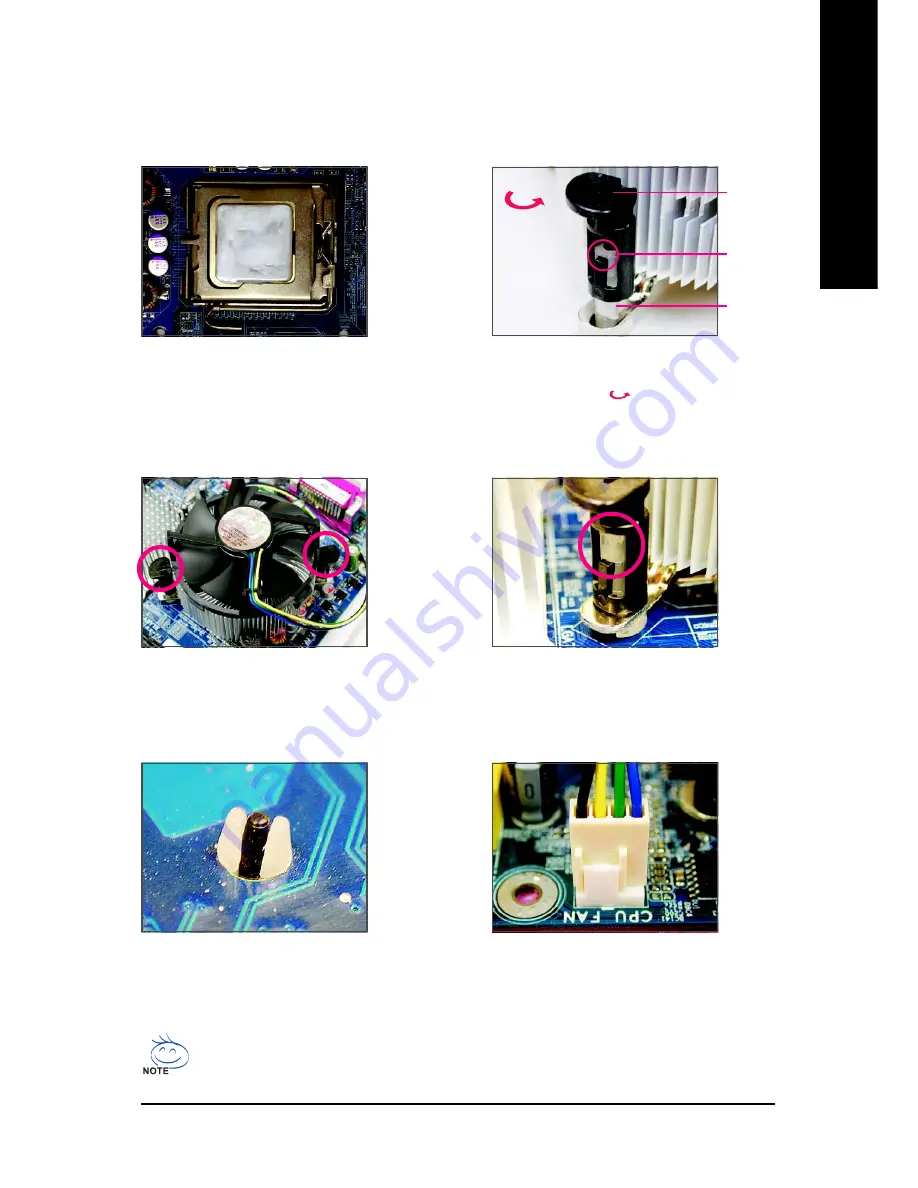
Place the cooler atop the CPU, aligning the
four push pins through the pin holes on the
motherboard. Push down on the push pins
diagonally.

Step 4:
You should hear a "click" when pushing down each
push pin. Check that the Male and Female push pins
are joined closely. (Refer to your CPU cooler instal-
lation manual for instructions on installing the cooler.)

Step 5:
After the installation, check the back of the
motherboard. If the push pin is inserted as the
picture above, the installation is complete.

Step 6:
Finally, attach the power connector of the CPU
cooler to the CPU fan header (CPU_FAN) on
the motherboard.

1-3-2 Installing the CPU Cooler

Follow the steps below to correctly install the CPU cooler on the motherboard. (The following procedure
uses Intel

®

 boxed cooler as the example cooler.)

Step 1:
Apply an even and thin layer of thermal grease
on the surface of the installed CPU.

Step 2:
Before installing the cooler, note the direction
of the arrow sign 

on the male push pin.

(Turning the push pin along the direction of
arrow is to remove the cooler, on the contrary,
is to install.)

Male

Push Pin

Female

Push Pin

The Top

of Female

Push Pin

Direction of

the Arrow Sign

on the Male

Push Pin

Содержание GA-P35-DS3

Страница 1: ...ly User s Manual Rev 1003 12ME P35DS3 1003R The WEEE marking on the product indicates this product must not be disposed of with user s other household waste and must be handed over to a designated col...

Страница 2: ...Motherboard GA P35 DS3 GA P35 S3 Apr 25 2007 Motherboard GA P35 DS3 GA P35 S3 Apr 25 2007...

Страница 3: ...orm or by any means without GIGABYTE s prior written permission Documentation Classifications Inordertoassistintheuseofthisproduct GIGABYTEprovidesthefollowingtypesofdocumentations For quick set up of...

Страница 4: ...4 2 Installing a Memory 17 1 5 Installing an Expansion Card 18 1 6 InstallingtheSATABracket 19 1 7 Back Panel Connectors 20 1 8 InternalConnectors 22 Chapter 2 BIOS Setup 33 2 1 StartupScreen 34 2 2 T...

Страница 5: ...5 69 4 4 Windows Vista ReadyBoost 70 Chapter 5 Appendix 71 5 1 Configuring SATA Hard Drive s 71 5 1 1 Configuring GIGABYTE SATA2 SATA Controller 71 5 1 2 Making a SATA RAID AHCI Driver Diskette 78 5...

Страница 6: ...ve cable Two SATA 3Gb s cables GA P35 DS3 One SATA bracket I O Shield The box contents above are for reference only and the actual items shall depend on product package you obtain The box contents are...

Страница 7: ...SPDIF_I CI DDRII1 DDRII2 DDRII3 DDRII4 BATTERY GSATAII0 F_PANEL IT8718 SYS_FAN2 SATAII0 ATX_12V Intel P35 Intel ICH9 PWR_LED FDD PCIE_2 SATAII1 SATAII4 SATAII5 GIGABYTE SATA2 PCI1 PCI2 PCI3 USB CLR_CM...

Страница 8: ...100 MHz PCI Express x16 12 USB Ports IT8718 Floppy PS 2 KB Mouse LPT Port CPU CLK 333 266 200 MHz Center Subwoofer Speaker Out Line Out MIC Line In SPDIF In SPDIF Out Side Speaker Out Surround Speaker...

Страница 9: ...ur hands dry and first touch a metal object to eliminate static electricity Prior to installing the motherboard please have it on top of an antistatic pad or within a electrostaticshieldingcontainer B...

Страница 10: ...00 667 MHz memory modules Go to GIGABYTE s website for the latest memory support list Audio Realtek ALC889A codec High Definition Audio 2 4 5 1 7 1 channel Support for S PDIF In Out Support for CD In...

Страница 11: ...ader Back Panel 1 x PS 2 keyboard port Connectors 1 x PS 2 mouse port 1 x parallel port 1 x coaxial S PDIF Out connector 1 x optical S PDIF Out connector 1 x serial port 4 x USB 2 0 1 1 ports 1 x RJ 4...

Страница 12: ...tion when more than 4 GB of physical memory is installed the actual memory size displayed will be less than 4 GB Note 2 To enable hot plug capability for the SATA connectors SATAII0 SATAII1 SATAII4 SA...

Страница 13: ...It is not recom mended that the system bus frequency be set beyond hardware specifications since it does not meet the standard requirements for the peripherals If you wish to set the fre quency beyon...

Страница 14: ...CPU socket or you may align the CPU notches with the socket alignment keys and gently insert the CPU into position Step 3 Lift the metal load plate on the CPU socket Step 5 Once the CPU is properly in...

Страница 15: ...tion check the back of the motherboard If the push pin is inserted as the picture above the installation is complete Step 6 Finally attach the power connector of the CPU cooler to the CPU fan header C...

Страница 16: ...e will double the original memory bandwidth The four DDR2 memory sockets are divided into two channels and each channel has two memory sockets as following Channel 0 DDRII1 DDRII2 Channel 1 DDRII3 DDR...

Страница 17: ...o the memory socket Notch DDR2 DIMM Step 2 The clips at both ends of the socket will snap into place when the memory module is securely inserted A DDR2 memory module has a notch so it can only fit in...

Страница 18: ...ted in the slot 3 Make sure the metal contacts on the card are completely inserted into the slot 4 Secure the card s metal bracket to the chassis back panel with a screw 5 After installing all expansi...

Страница 19: ...onnec tors when installing Step 1 Locate one free PCI slot and secure the SATA bracket to the chassis back panel with a screw Follow the steps below to install the SATA bracket Step 2 Connect the SATA...

Страница 20: ...in connector Serial Port Use the serial port to connect devices such as a mouse modem or other peripherals USB Port The USB port supports the USB 2 0 1 1 specification Use this port for USB devices su...

Страница 21: ...s in a 5 1 7 1 channel audio configuration Rear Speaker Out Jack Black Use this audio jack to connect rear speakers in a 4 5 1 7 1 channel audio configuration Side Speaker Out Jack Gray Use this audio...

Страница 22: ...e power cord from the power outlet to prevent damage to the devices After installing the device and before turning on the computer make sure the device cable has been securely attached to the connecto...

Страница 23: ...t To meet expansion requirements it is recommended that a power supply that can withstand high power consumption be used 400W or greater If a power supply is used that does not provide the required po...

Страница 24: ...orientation Most fans are designed with color coded power connector wires A red power connector wire indicates a positive connection and requires a 12V voltage The black connector wire is the ground...

Страница 25: ...the role of the IDE devices for example master or slave For information about configuring master slave settings for the IDE devices read the instructions from the device manufacturers 2 40 1 39 9 SAT...

Страница 26: ...S5 Off 10 GSATAII0 1 SATA 3Gb s Connectors Controlled by GIGABYTE SATA2 Purple The SATA connectors conform to SATA 3Gb s standard and are compatible with SATA 1 5Gb s standard Each SATA connector supp...

Страница 27: ...lue Connects to the hard drive activity LED on the chassis front panel The LED is on when the hard drive is reading or writing data RES Reset Switch Green Connects to the reset switch on the chassis f...

Страница 28: ...GND 3 MIC2_R 4 ACZ_DET 5 LINE2_R 6 FSENSE1 7 FAUDIO_JD 8 No Pin 9 LINE2_L 10 FSENSE2 For HD Front Panel Audio The front panel audio header supports HD audio by default If your chassis provides an AC...

Страница 29: ...GND 8 GND 9 No Pin 10 NC Do not plug the IEEE 1394 bracket 2x5 pin cable into the USB header Prior to installing the USB bracket be sure to turn off your computer and unplug the power cord from the po...

Страница 30: ...r cord from the power outlet before clearing the CMOS values After clearing the CMOS values and before turning on your computer be sure to remove the jumper cap from the jumper Failure to do so may ca...

Страница 31: ...place of purchase or local dealer if you are not able to replace the battery by yourself or uncertain about the battery model When installing the battery note the orientation of the positive side and...

Страница 32: ...GA P35 DS3 S3 Motherboard 32 English...

Страница 33: ...sily upgrade or back up BIOS without entering the operating system BIOS is a Windows based utility that searches and downloads the latest version of BIOS from the Internet and updates the BIOS For ins...

Страница 34: ...e first boot device then press Enter to accept To exit Boot Menu press Esc The system will directly boot from the device configured in Boot Menu Note The setting in Boot Menu is effective for one time...

Страница 35: ...ht submenus only F5 Restore the previous BIOS settings for the current submenus F6 Load the Fail Safe BIOS default settings for the current submenus F7 Load the Optimized BIOS default settings for the...

Страница 36: ...Power Management Setup Use this menu to configure all the power saving functions PnP PCI Configurations Use this menu to configure the system s PCI PnP resources PC Health Status Use this menu to see...

Страница 37: ...ions are Auto default CHS LBA Large IDE Channel 2 3 Master IDE Channel 4 5 Master Slave IDE Auto Detection Press Enter to autodetect the parameters of the IDE SATA device on this channel Extended IDE...

Страница 38: ...ive is 3 mode floppy disk drive a Japanese standard floppy disk drive Options are Disabled default Drive A Halt on Allows you to determine whether the system will stop for an error during the POST No...

Страница 39: ...BIOS Setup program HDD S M A R T Capability Enables or disables the S M A R T Self Monitoring and Reporting Technology capability of your hard drive This feature allows your system to report read writ...

Страница 40: ...nction When enabled the CPU core frequency and voltage will be reduced when the CPU is overheated Default Enabled CPU EIST Function Note Enables or disables Enhanced Intel SpeedStep Technology EIST De...

Страница 41: ...s to operate in Native IDE mode Enable Native IDE mode if you wish to install operating systems that support Native mode e g Windows XP 2000 USB Controller Enables or disables the integrated USB contr...

Страница 42: ...diagnosing your LAN cable When No LAN Cable Is Attached If no LAN cable is attached to the motherboard the Status fields of all four pairs of wires will show Open and the Length fields show 0 0m as s...

Страница 43: ...ATA mode Onboard Serial Port 1 Enables or disables the first serial port and specifies its base I O address and corresponding interrupt Options are Auto 3F8 IRQ4 default 2F8 IRQ3 3E8 IRQ4 2E8 IRQ3 Dis...

Страница 44: ...r button is pressed for less than 4 seconds the system will enter suspend mode PME Event Wake Up Allows the system to be awakened from an ACPI sleep state by a wake up signal from a PCI or PCIe device...

Страница 45: ...les this function Default Double Click Double click on left button on the PS 2 mouse to turn on the system Power On By Keyboard Allows the system to be turned on by a PS 2 keyboard wake up event Note...

Страница 46: ...Assigns IRQ 3 4 5 7 9 10 11 12 14 15 to the second PCI slot PCI3 IRQ Assignment Auto BIOS auto assigns IRQ to the third PCI slot Default 3 4 5 7 9 10 11 12 14 15 Assigns IRQ 3 4 5 7 9 10 11 12 14 15 t...

Страница 47: ...for CPU temperature When CPU temperature exceeds the threshold BIOS will emit warning sound Options are Disabled default 60o C 140o F 70o C 158o F 80o C 176o F 90o C 194o F CPU SYSTEM POWER FAN Fail...

Страница 48: ...Specifies how to control CPU fan speed This item can not be configured if Smart FAN Control Method is set to Disabled Auto Lets BIOS autodetect the type of CPU fan installed and sets the optimal CPU f...

Страница 49: ...ss Frequency Mhz Auto C I A 2 Disabled System Memory Multiplier SPD Auto Memory Frequency Mhz 667 667 High Speed DRAM DLL Settings Option 1 System Voltage Optimized System Voltage Control Manual DDR2...

Страница 50: ...y by 9 or 11 depending on CPU loading Turbo Increases CPU frequency by 15 or 17 depending on CPU loading Full Thrust Increases CPU frequency by 17 or 19 depending on CPU loading Warning Before using C...

Страница 51: ...ou to set the Front Side Bus voltage Normal Supplies the FSB voltage as required Default 0 1V 0 3V Increases FSB voltage by 0 1V to 0 3V at 0 1V increment G MCH OverVoltage Control Allows you to set t...

Страница 52: ...ults Load Optimized Defaults Set Supervisor Password Set User Password Save Exit Setup Exit Without Saving Load Optimized Defaults Y N N Press Enter on this item and then press the Y key to load the o...

Страница 53: ...ogram allows you to specify two separate passwords Supervisor Password When a system password is set and the Password Check item in Advanced BIOS Features is set to Setup you must enter the supervisor...

Страница 54: ...1984 2007 Award Software Standard CMOS Features Advanced BIOS Features Integrated Peripherals Power Management Setup PnP PCI Configurations PC Health Status MB Intelligent Tweaker M I T ESC Quit KLJI...

Страница 55: ...shown in the screen shot below If the driver Autorun screen does not appear automatically go to My Computer double click the optical drive and execute the Run exe program Some device drivers will res...

Страница 56: ...e displays all the tools and applications that GIGABYTE develops and some free software You may press the Install button following an item to install it 3 3 Driver CD Information This page provides in...

Страница 57: ...are Information This page provides information about the hardware devices on this motherboard 3 5 Contact Us Check the contacts information of the GIGABYTE headquarter in Taiwan and the overseas branc...

Страница 58: ...GA P35 DS3 S3 Motherboard 58 English...

Страница 59: ...hard drive for the operating system Xpress Recovery2 can only back up restore the first physical hard drive that has the operating system installed As Xpress Recovery2 will save the backup file at th...

Страница 60: ...as the example operating system A Installing Windows XP and Partitioning the Hard Drive 1 Set CD ROM drive as the first boot device under Advanced BIOS Features in the BIOS Setup program Save the cha...

Страница 61: ...stall the operating system and re partition your hard drive Figure 7 4 After the operating system is installed right click the My Computer icon on your desktop and select Manage Figure 4 Go to Compute...

Страница 62: ...ou wish to enter Xpress Recovery2 later simply press F9 during the POST Figure 9 Figure 8 Figure 9 B Accessing Xpress Recovery2 1 Boot from the motherboard driver disk to access Xpress Recovery2 for t...

Страница 63: ...Management and hard drive space will be freed up Figure 16 Figure 15 Figure 16 D Using the Restore Function in Xpress Recovery2 Select RESTORE to restore the backup to your hard drive in case the syst...

Страница 64: ...P35 BIOS for P35 DS3 F1b DEL BIOS Setup Q Flash F9 XpressRecovery2 F12 Boot Menu End Qflash 04 10 2007 P35 ICH9 6A79OG0NC 00 Because BIOS flashing is potentially risky please do it with caution Inadeq...

Страница 65: ...Flash only supports USB flash drive or hard drives using FAT32 16 12 file system If the BIOS update file is saved to a hard drive in RAID AHCI mode or a hard drive attached to an independent IDE SATA...

Страница 66: ...s and press Enter to load BIOS defaults System will re detect all peripherals devices after a BIOS update so we recommend that you reload BIOS defaults CMOS Setup Utility Copyright C 1984 2007 Award S...

Страница 67: ...Select this option Click Update New BIOS 4 2 2 Updating the BIOS with the BIOS Utility A Before You Begin 1 If your system supports Intel Hyper Threading technology disable this function in BIOS Setu...

Страница 68: ...board model Updating the BIOS with an incorrect BIOS file could result in an unbootable system If the BIOS update file for your motherboard is not present on the BIOS server site please manually downl...

Страница 69: ...cing the performance of these components Button Display Description 1 OVERCLOCKING Enters the Overclocking setting page 2 C I A M I B Enters the C I A and M I B setting page 3 SMART FAN Enters the Sma...

Страница 70: ...o enable the ReadyBoost function Step 1 Go to Computer Right click on the USB flash drive icon and choose Properties Step 2 In the ReadyBoost tab select Use this device Under Space to reserve for syst...

Страница 71: ...nce it is recommended that you use two hard drives with identical model and capacity If you do not want to create RAID you may prepare only one hard drive An empty formatted floppy disk Windows Vista...

Страница 72: ...erboard The actual BIOS Setup menu options you will see shall depend on the motherboard you have and the BIOS version CMOS Setup Utility Copyright C 1984 2007 Award Software Integrated Peripherals SAT...

Страница 73: ...ODD0 DVDROM GO D1600B Press Ctrl G to enter RAID Setup Utility In the main screen of the GIGABYTE SATA2 RAID BIOS utility Figure 3 use the up or down arrow key to highlight through choices in the Mai...

Страница 74: ...GABYTE Technology Corp PCIE to SATAII IDE RAID Controller BIOSv1 06 59 Create New RAID Name GRAID Level 0 Stripe Disks Select Disk Block 128 KB Size 240 GB Confirm Creation RAID Disk Drive List KL Swi...

Страница 75: ...which will be used to divide data from to seperate RAID members The following are typical values RAID 0 128KB Figure 7 5 Set Array Size Under the Size item enter the size of the array and press Enter...

Страница 76: ...y Corp PCIE to SATAII IDE RAID Controller BIOSv1 06 59 Main Menu Create RAID Disk Drive Delete RAID Disk Drive Revert HDD to Non RAID Solve Mirror Conflict Rebuild Mirror Drive Save And Exit Setup Exi...

Страница 77: ...Drive Delete RAID Disk Drive Revert HDD to Non RAID Solve Mirror Conflict Rebuild Mirror Drive Save And Exit Setup Exit Without Saving RAID Disk Drive List KL Select RAID SPACE Mark Delete DEL Confir...

Страница 78: ...startup disk Once at the A prompt change to your optical drive example D At the D prompt type the following two commands Press Enter after each command Figure 1 cd bootdrv menu Step 2 When the control...

Страница 79: ...for which you have a device support disk from a mass storage device manufacturer press S If you do not have any device support disks from a mass storage device manufacturer or do not want to specify...

Страница 80: ...2003 To specify additional SCSI adapters CD ROM drives or special disk controllers for use with Windows including those for which you have a device support disk from a mass storage device manufacture...

Страница 81: ...Figure 5 WindowsXP Professional Setup Enter Continue R Repair F3 Exit Welcome to Setup This port of the Setup program prepares Microsoft R Windows R XP to run on your computer To set up Windows XP no...

Страница 82: ...er Subwoofer Speaker Out Side Speaker Out Line In Front Speaker Out Mic In High Definition Audio HD Audio HD Audio includes multiple high quality digital to analog converters DACs that support 44 1KHz...

Страница 83: ...en click OK to complete the configuration B Configuring Sound Effect You may configure an audio environment on the Sound Effect tab C Configuring AC 97 Audio If you want to connect an AC 97 front pane...

Страница 84: ...First attach the connector at the end of the cable to the SPDIF_IN header on your motherboard Step 2 Secure the metal bracket to the chassis back panel with a screw S PDIF In The S PDIF in jacks allo...

Страница 85: ...tput source Click OK to complete the configuration S PDIF Out The S PDIF out jacks can transmit audio signals to an external decoder for decoding to get the best audio quality Connect a S PDIF coaxial...

Страница 86: ...tionality Note The microphone functions on the front panel and back panel cannot be used at the same time Step 3 Locate the Volume icon in your system tray and click it to open the volume control pane...

Страница 87: ...eck box under Front Pink In or Front Green In in Master Volume It is recommended that you set the volume at a middle level To hear the sound being recorded during the record ing process when using the...

Страница 88: ...begin the sound recording 5 2 4 Using the Sound Recorder Recording the Sound 1 Make sure you have connected the audio input device e g microphone to the computer 2 On the File menu choose New 3 To rec...

Страница 89: ...ut one minute Refer to the steps below Steps 1 Turn off your computer and unplug the power cord 2 Gently remove the battery from the battery holder and wait for one minute Or use a metal object like a...

Страница 90: ...emory is installed properly on the memory slot Yes Yes START Make sure the motherboard does not short circuit with the chassis or other metal objects Insertthegraphicscard ConnecttheATXmainpowercablea...

Страница 91: ...The keyboard or mouse might fail A Turn off the computer and connect the IDE SATA devices Check if the system can boot successfully Press Delete to enter BIOS Setup Select Load Fail Safe Defaults or...

Страница 92: ...GA P35 DS3 S3 Motherboard 92 English...

Страница 93: ...Appendix 93 English...

Страница 94: ...abyte usa com Web address http www gigabyte com mx Singapore GIGA BYTE SINGAPORE PTE LTD WEB address http www gigabyte com sg Thailand WEB address http th giga byte com Vietnam WEB address http www gi...

Страница 95: ...abyte com tr To submit a technical or non technical Sales Marketing question please link to http ggts gigabyte com tw Then select your language to enter the system Russia Moscow Representative Office...

Страница 96: ...96...

Отзывы: