


System Hardware Installation
- 27 -
3-2 Installing the CPU and Heat Sink
Read the following guidelines before you begin to install the CPU:
• Make sure that the motherboard supports the CPU.
• Always turn off the computer and unplug the power cord from the power outlet before installing
the CPU to prevent hardware damage.
• Unplug all cables from the power outlets.
• Disconnect all telecommunication cables from their ports.
• Place the system unit on a flat and stable surface.
• Open the system according to the instructions.
WARNING!
Failure to properly turn off the server before you start installing components may cause serious
damage. Do not attempt the procedures described in the following sections unless you are a
qualified service technician.
Follow these instructions to install the CPU:
1. Align and install the processor on the carrier, making sure to line up the triangle markers on the
corner of the CPU to the triangle mark on the corner of the CPU carrier.
2. Slide the carrier assembly into the channels of the carrier bracket
3.
Close the carrier bracket so that it firmly latches on to the CPU socket.
4. Close the CPU socket cover.
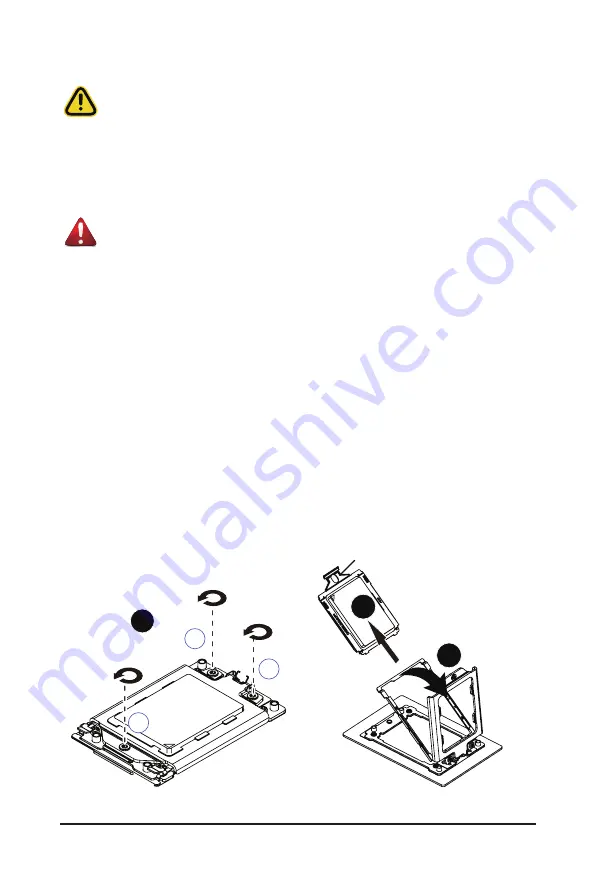
5. Tighten and secure the CPU socket cover screws in the following order (3
g
2
g
1).
NOTE:
When removing the CPU socket cover, loosen the screws in reverse order (1
g
2
g
3).
NOTE:
Apply thermal compound evenly on the top of the CPU. Remove the protective cover from
the underside of the heat sink.
6. Align and place the heatsink onto the top of the CPU socket.
7. To secure the heatsink, tighten the four screws to the CPU socket.
8. Repeat steps 1-7 for the second CPU and heatsink.
9. To remove the heatsinks and CPUs, follow steps 1-7 in reverse order.
33
11
22
1
External cap
2
3
Содержание G152-Z12
Страница 1: ...G152 Z12 HPC Server 1U UP Gen4 GPU Server User Manual Rev 1 0 ...
Страница 10: ... 10 This page intentionally left blank ...
Страница 15: ... 15 Hardware Installation 1 3 System Block Diagram ...
Страница 38: ... 38 System Hardware Installation Motherboard Power Cable PMBus Cable ...
Страница 39: ...System Hardware Installation 39 Management LAN Signal Cable OCP 3 Signal Cable ...
Страница 40: ...System Hardware Installation 40 HDD Backplane Board Power Cable HDD Backplane Board Signal Cable ...
Страница 41: ...System Hardware Installation 41 GPU Riser Card Power Cable GPU Signal Cable ...
Страница 42: ...System Hardware Installation 42 NVMe 1 2 Cable Top Bottom NVMe 3 4 Cable Top Bottom ...
Страница 51: ...BIOS Setup 51 When Boot Mode Select is set to Legacy in the Boot Boot Mode Select section ...
Страница 56: ...BIOS Setup 56 5 2 4 1 Serial Port 1 Configuration ...
Страница 64: ...BIOS Setup 64 5 2 8 PCI Subsystem Settings ...
Страница 75: ...BIOS Setup 75 5 2 17 Intel R Ethernet Controller X550 ...
Страница 81: ...BIOS Setup 81 5 3 1 CPU Common Options ...
Страница 94: ...BIOS Setup 94 5 3 3 1 1 Enforce POR ...
Страница 140: ...BIOS Setup 140 This page intentionally left blank ...