10
9. The rear V-sleeve housing
(48) may be removed by
prying evenly outward with a
flat screwdriver. After slipping
housing over plunger, inspect
rear v-sleeves (50), support
rings (51) and O-ring (49) and
replace as necessary.
10.Inspect ceramic plunger
(24A) tips for wear. If
necessary, replacement of
the ceramic plungers may be
accomplished by removing
the plunger bolt assemblies
(24B and 24C) with a 13mm
wrench. Ceramic plungers
should now slide off the
stainless steel plunger base
(22). Excessive resistance
to plunger removal may be
overcome by heating the
stainless steel plunger base.
This will melt any excess
loc-tite beneath the ceramic
plunger allowing easy
removal.
NOTE: Contact Giant Industries for Service School Information. Phone: (419)-531-4600
REPAIR INSTRUCTIONS - P46W, P46W-HK, & P46HT
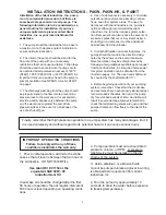
8. The pressure rings (item 30) can now be removed by pulling straight
out. Inspect and clean manifold (29) and pressure ring. Replace if
necessary. From the front of the pump reinstall pressure rings into
manifold (29) with grooved side towards front of manifold. Install new
v-sleeves (31), with grooved sides towards front of pump. For P46W-
HK & P46HT pumps, install high temperature seal (50) before v-sleeve
(31) with grooved sides towards front of pump. Replace the support
rings (32) and pressure springs (33) into manifold (29). Install valve
assembly (34-40) into manifold (29). Reinstall manifold plugs (43) and
torque plugs to 52 ft.-lbs.
30
50
31
32
38
33
(P46W-HK & P46HT only)
49
50
51
11.Replace copper ring (24C)
onto plunger bolt (24B).
Slide plunger bolt assembly
into ceramic plunger (24A).
Apply a light film of loc-tite to
plunger bolt threads and
place plunger assembly onto
stainless steel plunger base
(22) and tighten to 105 in.-
lbs.
12.To replace plunger oil seals
(26), proceed to “Gear End
Disassembly” section below.
Otherwise, continue as
described below.
24C
13.Before replacing pump manifold
(29), first rotate crankshaft (18)
until two outside plungers (24A)
extend evenly forward. Next
lubricate rear v-sleeves (50)
and support ring (51) in the rear
v-sleeve housing (48) and slide
housing over plungers. Lubri-
cate ceramic plungers with a
light film of oil. Carefully and
evenly slide manifold over
plungers and press manifold
firmly against crankcase (1).
Replace manifold stud bolts
(45), washers (47) and nut (46)
and tighten to 35 ft.-lbs.
Содержание P46HT
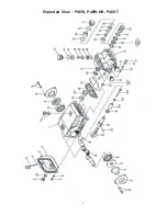
Страница 6: ...6 Exploded View P46W P46W HK P46HT...


