background image

7

6)  Loosen the 8 nuts (49A) 

with a 19mm socket and 

pull off valve casing (43) 


to the front.

TO CHECK SEALS AND PLUNGER PIPE

7) 

Remove the seal sleeve 

(35) from the manifold 

and /or crankcase. 


8)  Remove  seal  case  (37) 

from seal sleeve (35).


9) 

Check O-rings (39 & 38) and support rings (39A & 

38A) on seal case (37). 


39 

39A 

37 

38A 

     38

10) Remove  leakage  seal 

(36) from the seal sleeve. 

If  worn  or  damaged  re-

place with new seal.


11) 

Remove the pressure ring (40A), v-sleeves (40/40C), 

sleeve, and support ring (40B), 

from the seal sleeve. 

Remove the pressure spring (41). Examine seals careful-

ly and replace if worn. 

Clean surfaces of seal sleeves 

(35) which come in contact with the crankcase (1) 

and sealing surfaces of valve casing (43).


35 

40A 

40 

    40C 

   40B

REPAIR INSTRUCTIONS - LP301A-0081  

NOTE:


Always take time to lubricate all metal and non-metal parts with a light film of oil before reassembling.  

This step will help ensure proper fit, at the same time protecting the pump non-metal parts (elastomers) from 

cutting and scoring.

Содержание LP301A-0081

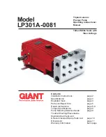
Страница 1: ...s page 6 9 Torque Specifications page 9 Pump Mounting Selection Guide page 9 Trouble Shooting Preventative Maintenance Check List Recommended Spare Parts List page 10 Dimensions page 11 Warranty Infor...

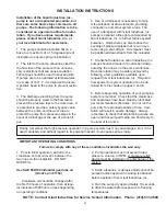
Страница 2: ...pproximately 10 seconds to drain the water before exposure to freezing temperatures 1 Prior to initial operation add oil to the crankcase so that oil level is between the two lines on the oil dipstick...

Страница 3: ...ic pump horsepower requirements use the following formula HP GPM X PSI 1450 U S Metric Flow 14 2 GPM 53 6 LPM Pressure 4000 PSI 275 bar Speed 1000 RPM 1000 RPM Inlet Pressure 4 35 to 145 PSI 0 3 to 10...

Страница 4: ...ss steel valve plugs 48 can seize when being screwed out of the cas ing To release tension beforehand strike the plugs 1 2 times with a steel hammer on the top before screwing them out Coat threads wi...

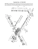
Страница 5: ...ing for Bearing Cover 2 17 07114 Hexagon Screw 8 20 07116 Taper Roller Bearing 2 20A 07117 Fitting Disc 1 3 20B 13001 Fitting Disc 1 3 21 05376 Shaft Protector 1 21A 05377 Shaft Guard Holder 1 22 1324...

Страница 6: ...ing 44A and tension spring 45 3 Take out discharge valve assemblies 46 by pulling them upwards out of the valve casing 43 with a snap ring tongs or any other pull off device Then remove inlet valves i...

Страница 7: ...new seal 11 Remove the pressure ring 40A v sleeves 40 40C sleeve and support ring 40B from the seal sleeve Remove the pressure spring 41 Examine seals careful ly and replace if worn Clean surfaces of...

Страница 8: ...eramic plunger side and tighten screw to 265 in lbs 30 NM 29B 29D 29C 13 Replace complete seal sleeve 35 seal case 37 assembly into crankcase 1 Make sure that the weep hole points down ward Note To re...

Страница 9: ...he crankcase To Reassemble Using a soft tool press in the outer bearing ring until the outer edge lines up with the outer edge of the bear ing hole Remove bearing cover 14 together with radial shaft s...

Страница 10: ...nlet of pump for restrictions Unloader Check for proper operation Water in crankcase High humidity Reduce oil change interval Worn seals Replace seals Noisy Operation Worn bearings Replace bearings Re...

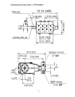
Страница 11: ...11 Dimensions Inches mm LP301A 0081...

Страница 12: ...and tear to standard wear parts 3 Use of repair parts other than those manufactured or authorized by Giant 4 Improper use of the product as a component part 5 Changes or modifications made by the cust...

Отзывы: