background image

Pump Repair Instructions - GP8055/GP8060/GP8065 - Brine

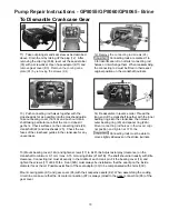
12) Remove the connecting rod screws (24).

 Connecting rods are marked 1 to 

3 for identification. Do not twist connecting rod 

halves or interchange them. When reassembling, 

the connecting rod must be fitted in their exact 

original position on the crankshaft journals.

13)  Push connecting rod halves together with the 

crosshead as far as possible into the crosshead guide. 

Take out bearing cover (14/14A) and push out crank-

shaft taking particular care that the con rod doesn’t 

get bent.  Check surfaces on the connecting rods (24), 

crankshaft (22) and crossheads (25).  Check the sur-

faces of the crosshead guides in the crankcase for any 

unevenness. 

15) Mount bearing cover (14A) and tighten screws (17) to 64 Ft-lbs. Adjust axial play (clearance) on the 

crankshaft to minimum 0.1 mm / max. 0.15 mm using shims (21A/21B). The shaft should turn easily with little 

clearance. Connecting rod must sit exactly in the middle of each crank pin. Fit the bearing cover (14) and 

tighten the screws (17) at 64 Ft-lbs.  Seal (32A) must always be installed so that the seal lip on the inside 

diameter faces the oil. Possible axial float of the seal adaptor (33) to be compensated with shims (33C).

Mount cooling plate (K1) and gear cover (K3) with their respective seals (K2). When assembling the cooling 

circuit line, make sure that the oil cooler connection (K7) is always joined to the 

upper

 connection (K3) of the 

gear cover.

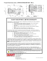
14)  Reassemble in reverse order. Thread the 

long end of the crankshaft together with the inner 

bearing rings into the crankcase; then mount 

outer bearing ring (20) and spacer ring (22A).  

Mount connecting rod halves in their exact origi

-

nal position and tighten at 37 Ft-lbs.

 Connecting rods must be able to 

move slightly sideways on the stroke journals.

To Dismantle Crankcase Gear

11)


Take out plungers and seal sleeves as described 

above. Drain the oil by taking off the plug (12).  After 

removing the clip ring (33B), lever out the seal retainer 

(33) with a screwdriver. Open hose adaptor (K11) and 

remove gear cover (K3).  

Remove the cooling vane 

plate (K1) by removing the screws (K4)

11

Содержание GP8055-Brine

Страница 1: ...s List pages 6 7 Repair Kits Tool List page 8 Torque Specifications page 8 Troubleshooting Chart page 8 Repair Instructions pages 9 11 Dimensions back page Warranty Information back page Triplex Ceram...

Страница 2: ...and is approximately 1 85 GPM 7 0 L min at 580 RPM The cooling water is sucked in by one of the pumping chambers and pumped away The stated figures are for maximum pressure and maximum speed RPM and a...

Страница 3: ...cted in this case Specifications Model GP8055 Brine Consult the factory for special requirements that must be met if the pump is to operate beyond one or more of the limits specified above HORSEPOWER...

Страница 4: ...ontacted in this case Specifications Model GP8060 Brine Consult the factory for special requirements that must be met if the pump is to operate beyond one or more of the limits specified above HORSEPO...

Страница 5: ...contacted in this case Specifications Model GP8065 Brine Consult the factory for special requirements that must be met if the pump is to operate beyond one or more of the limits specified above HORSEP...

Страница 6: ...6 Exploded View GP8055 GP8060 GP8065 Brine...

Страница 7: ...ng 3 40 07723 Seal Ring GP8055 3 40 05067 Seal Ring GP8060 3 Item Part Description Qty 40 06996 Seal Ring GP8065 3 41 05276 Pressure Ring GP8055 3 41 05068 Pressure Ring GP8060 3 41 05117 Pressure Rin...

Страница 8: ...g examine valve casing for unevenness on the sealing surfaces Oil leaks at visible part of plunger Gear sealing is leaky Examine seals and running surface of plunger Dirty mile colored frothy oil Oil...

Страница 9: ...t with silicon grease or molycote anti seize Cu 7439 when reassembling Be fore refitting the valves clean the sealing sur faces in the casing and check for any damage Tighten caps 58 at 133 Ft lbs che...

Страница 10: ...other side of the seal sleeve 9 Coat the seal sleeve lightly with anti corrosive grease e g molycote no Cu 7439 in its fitted area towards the crankcase Insert the seal sleeves in to their crankcase f...

Страница 11: ...of each crank pin Fit the bearing cover 14 and tighten the screws 17 at 64 Ft lbs Seal 32A must always be installed so that the seal lip on the inside diameter faces the oil Possible axial float of t...

Страница 12: ...tries Inc Liability under this warranty is on all non wear parts and limited to the replacement or repair of those products returned freight prepaid to Giant Industries which are deemed to be defectiv...

Отзывы: