7
To Check Valves
Discharge Valves: remove valve plugs (52) using allen wrench. Using a screwdriver, carefully push the exposed
spring tension cap (51A) to the side to remove it from the valve seat (51D). Take out the spring tension cap,
valve spring (51B) and valve plate (51C). Pull out valve seat (51D) using an extractor tool (ø12-ø16 mm).
To dismantle the complete valve, place a screwdriver through a gap in the spring tension cap, press on the valve
plate and lever the valve apart. Tighten plugs (52) at 107 ft.-lbs. (145 Nm).
Suction Valves: remove hexagon socket screws (60) and pull valve casing (50) past the plungers (29A-29E) and
to the front. Continue as described above under Discharge Valves.
Examine valves and replace worn parts.
To Check Seals and Plunger Pipe
Unscrew the 8 hexagon socket screws (60) and pull the valve casing (50) off to the front. Pull seal sleeves (33)
out of the guides in the crankcase. Remove seal case (46) from the seal sleeve (33) where necessary. Take
tension spring (43) and seal unit (39-42) out of the seal sleeve. Remove plugs (34). Check that the leakage
bores are free from deposits of all kinds. Check plunger surfaces and seals. Replace worn seals. After removing
support disc (31), check leakage seal (32) and replace if necessary. If the plunger surface is worn remove tension
screw (29D), clean the centring hole and the front of the plunger crosshead (25). Then carefully thread a new
plunger pipe through oiled seals into the seal sleeve. Put centring sleeve (29A) together with plunger extension
(29B) onto plunger crosshead (25). Place the seal sleeves together with the plunger pipe into the drive. Put a
new copper seal ring (29E) onto tension screw (29D). Lightly coat the threads of the tension screw as well as
the seal ring with glue (Loctite) and tighten at 26 ft.-lbs. (35 Nm).
Important!
Glue must never come between plunger extension (29B), plunger pipe (29C) and centring sleeve
(29A). Deformation of the plunger pipe due to excessive tightening of the tension screw or dirt or damage on
the front surface can cause the plunger pipe to fracture. The seal sleeves must be fitted so that grooved pins
(37) are on top. Put tension spring (43) into seal casing (33) and place the seal case (46) into the valve casing.
Carefully centre the valve casing with the fitted seal cases onto the seal sleeves and against the crankcase.
Then tighten hexagon socket screws (60) to 74-89 ft.-lbs. (100-120 Nm) to secure the valve casing.
To Dismantle Gear
Drain oil after dismantling valve casing and plunger pipes. Remove crankcase cover (4) and bearing cover (14).
Remove connecting rod screws (24), push the front connecting rod parts as far as possible into the crosshead
guide and carefully push out the radial shaft seals (31).
Important!
Do not twist the connecting rod halves. The connecting rods are marked for identification and must
be remounted onto the shaft journals in their exact original position.
Turn the crankshaft lightly and hit it out to one side using a rubber hammer.
Important!
Do not bend connecting rod shanks. Examine the surfaces of the crankshaft, connecting rods,
crossheads and plungers (25) as well as radial shaft seals (15, 31) and taper roller bearings (20) for wear.
To Reassemble
Using a soft tool, press in the outer bearing ring on one side until it lines up with the outer edge of the bearing
hole. Screw on the bearing cover together with shaft ring and o-ring. Fit the crankshaft with pressed-on bearing
parts through the bearing hole on the opposite side. Press in outer bearing ring and tension it inwards with the
bearing cover, keeping shaft in vertical position and turning it slowly so that the taper rollers of the bearings touch
the edge of the outer bearing ring. Adjust axial bearing clearance with shims 0.1 mm (20A). Shaft should turn
easily with very little clearance. Tighten hexagon socket screws on connecting rod (24) at 22 ft.-lbs. (30 Nm).
Important!
A little clearance must exist to enable slight sideward movement of the connecting rod on its
journal.
Important!
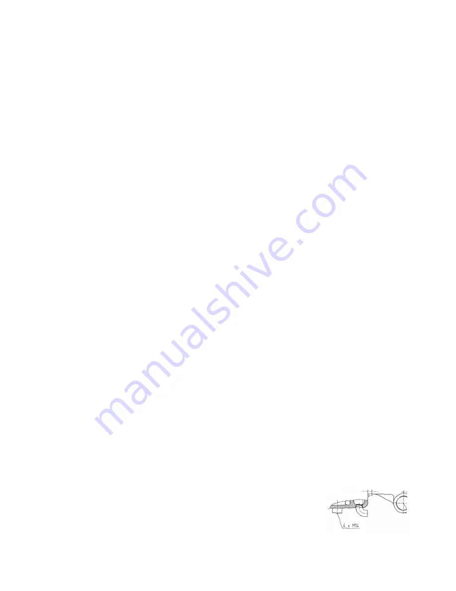
The 1/2” BSP connection in the crankcase serves the purpose of
draining leakage water. The connection should not be closed (see the drawing
to the right).
GP5120, GP5122 and GP5124 REPAIR INSTRUCTIONS
Содержание GP5122
Страница 4: ...4 EXPLODED VIEW GP5120 GP5122 GP5124 PUMPS...


