background image

32

31

www.giadatech.com

If this function is selected, the following information will appear:

Enter New Password hhhhhh

Then, enter the password with not more than eight characters and press 

<Enter>. BIOS will requires to enter the password again. Once you enter it 

again, BIOS will save the set password.

Once the password item is enabled, you will be required to enter the password 

each time before the system goes to the set program of BIOS. The user can set 

this item through the Security Option in advanced BIOS properties. If the item 

Security Option is set as System, the password will be required to be entered 

before the system guides and goes to the set program of BIOS. If set as Setup, 

the password will be required to be entered only before the system goes to the 

set program of BIOS.

To delete the password, press <Enter> in the popped-up window that requires to 

enter the password. Then, information for confirmation will appear on the screen 

to allow you decide whether the password is disabled. Once the password is 

disabled, you won’t have to enter the password and can enter the setup 

program directly when the system is restarted. 

Boot Sector Virus Protection

This item is used for setting the alarm function in the case of virus attack in IDE 

disk sector. If this item is set as Enable and some program wants to write 

information in the sector, BIOS will display alarm information on the screen and 

buzz.

·


Exit Options


The exit options include load optimal defaults/load failsafe defaults 

     value/discard changes/discard changes and exit.

·


Load failsafe defaults /optimal defaults


These two items can allow the user to restore all BIOS options to the failsafe 

     defaults and optimal defaults. The optimal defaults are set to optimize the 
     performance of the motherboard. The failsafe defaults are conservative  
     values for the system.
     If you enter OK and press Enter, all set values will be saved to CMOS SRAM 
     and the system will exit from the BIOS setup program. If you don’t want to  
     save, you can press Cancel or Esc to return to the main menu.

·


Discard Changes and Exit


If you enter OK and press Enter, the system will exit from the BIOS setup 

     program. If press Cancel or ESC, return to the main menu.

·


Discard Changes


If you enter OK and press Enter, the system will discard the changes. If  

     press Cancel or Esc, return to the main menu.
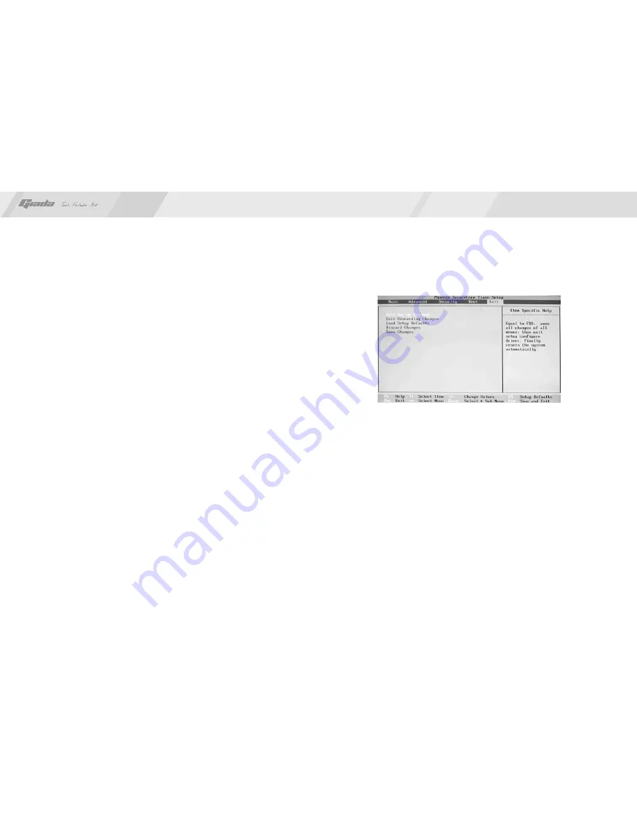
6. Exit

Fig 3.6

Содержание MI-D2700D

Страница 1: ...www giadatech com User s Manual MI D2700D N2600D All right reserved Version 001 Motherboard...

Страница 2: ...efinition 4 7 JLVDS 4 8 GPIO I II 4 9 VGA out 4 10 PS 2 out 4 11 AUTOPW_ON Pin Pin Contents BIOS setting 1 Main menu 2 Main Standard CMOS Setup 3 Advanced Advanced BIOS Setup 4 Boot Configuration 5 Se...

Страница 3: ...00D is based on Intel Atom Cedar Trail Processor and NM10 chipset It supports DDR3 1066 Dual channel memory on board HD AUDIO sound card and 2 1 gigabit LAN Support VGA display output and LVDS display...

Страница 4: ...off the power of the computer It is preferable the power cord be unplugged Take care not to contact the metal wires and theirs joints on the motherboard when handling it It is preferable that the oper...

Страница 5: ...19 JLVDS 20 JLVDS POWER 21 CPU_FAN 22 GPI 23 COM 2 6 24 PS 2 Pin out 25 PS 2 26 MINI_PCIE 1 2 4 7 10 17 18 19 22 5 20 16 3 6 8 9 11 12 13 14 15 21 23 24 25 2 Installing memory Please install the memor...

Страница 6: ...he card forward in the slot till the white buckle is automatically engaged in the concave hole at the two sides of the memory NOTE In order to avoid damages to the motherboard or the components the us...

Страница 7: ...memory of the motherboard The interruption the computer s power won t cause the loss of this information for the CMOS is powered by the battery on the motherboard The port is defined as follows 1 2 3...

Страница 8: ...sets of extension USB pins provided by this motherboard These ports support USB 2 0 devices The definitions of the ports are described below Definition VCC D2 D2 GND NC PIN 2 4 6 8 10 Definition VCC...

Страница 9: ...o connect to the wire harness of the audio adapter After connection you can easily control the audio output microphone through the front panel of the host Note Don t connect the wire to Pin 4 The defi...

Страница 10: ...B_TXDN3 GND GND LVDS_PWR PIN 2 4 6 8 10 12 14 16 18 20 22 24 26 28 30 Signal LVDS_A_TXDP0 LVDS_A_TXDP1 LVDS_A_TXDP2 GND LVDS_A_TXCP LVDS_A_TXDP3 LVDS_B_TXDP0 GND LVDS_B_TXDP1 LVDS_B_TXDP2 LVDS_B_TXCP...

Страница 11: ...0_1X12 I 1 1 2 2 3 3 4 4 5 5 6 6 7 7 8 8 9 9 10 10 11 11 12 12 G R 989 0 4 5 N C D D C_C LK B J2 HD 1 6P 2 0 I 1 1 2 2 3 3 4 4 5 5 6 6 PS2POWER KBDATA KBCLK MSCLK MSDATA Definition GPIO7 GPIO14 GPIO9...

Страница 12: ...PW_ON 3 1 PIN 2 54mm I 1 2 3 AUTO_PWR_ON BUTTON_PSW 1 11 10 20 Definition 3 3V 12V GND PS ON GND GND GND 5V 5V 5V PIN 11 12 13 14 15 16 17 18 19 20 Definition 3 3V 3 3V GND 5V GND 5V GND PG 5VSB 12V P...

Страница 13: ...on how to properly set the parameters in BIOS Therefore the correct setup of BIOS plays a key role in stably running the system and optimizing its performance The CMOS Setup will save the set paramete...

Страница 14: ...information disappears before you can act you can shut off the computer and turn on it again or you can press the key RESET on the machine case To restart your computer you can also simultaneously pre...

Страница 15: ...omputer with the format as week month day year Exit option of exit This item includes load optimal defaults load failsafe defaults value discard changes discard changes and exit 3 Advanced Advanced BI...

Страница 16: ...t appear However if the words wait appear during the start up process and you press Del the system can also enter CMOS for setup Hit Del Message Display Information is displayed when the computer is s...

Страница 17: ...can enter the setup program directly when the system is restarted Boot Sector Virus Protection This item is used for setting the alarm function in the case of virus attack in IDE disk sector If this i...

Страница 18: ...Install driver for motherboard After you complete the installation of the operating system you should then install the driver for the motherboard To this end put the disk into the CD ROM The interface...

Страница 19: ...log box as shown in Fig 4 3 will pop up Then you can click Next and wait till the driver is installed completely Fig 4 4 1 2 Install Sound card driver After you click Install behind the Realtek HD aud...

Страница 20: ...LAN Driver in the interface of Fig 4 2 a dialog box as shown in Fig 4 5 will pop up Then you can click Next and wait till the driver is installed completely Fig 4 5 2 HD AUDIO sound card setup For Wi...

Страница 21: ...state of microphone is mute You need to turn it on manually as shown in Fig 4 7 and 4 8 Fig 4 9 Fig 4 10 For Windows Vista After the driver for the audio adapter is installed you can click the Audio...

Страница 22: ...e controlling interface will turn to one shown in Fig 4 12 Fig 4 12 Fig 4 13 If a MIC is used please select the corresponding front or rear mode and set the device as default In the above interface yo...

Страница 23: ...lar installation If this equipment does cause harmful interference to radio or television reception which can be determined by turning the equipment off and on the user is encouraged to try to correct...

Отзывы: