E40.0.5X.6C-01
Operating Manual EASY
LOG
80IMP…
page 7 of 16
5. Electric connection
For the types
“active signal” mind the maximum input current rating of 2 mA
under any circumstances !
5.1 EASY
LOG
80IMP/
…
The connection of the logger occurs via 2-wire connection cable.
connection
number
wire colour
EASY
LOG
80IMP
1
red
2
transparent
signal -
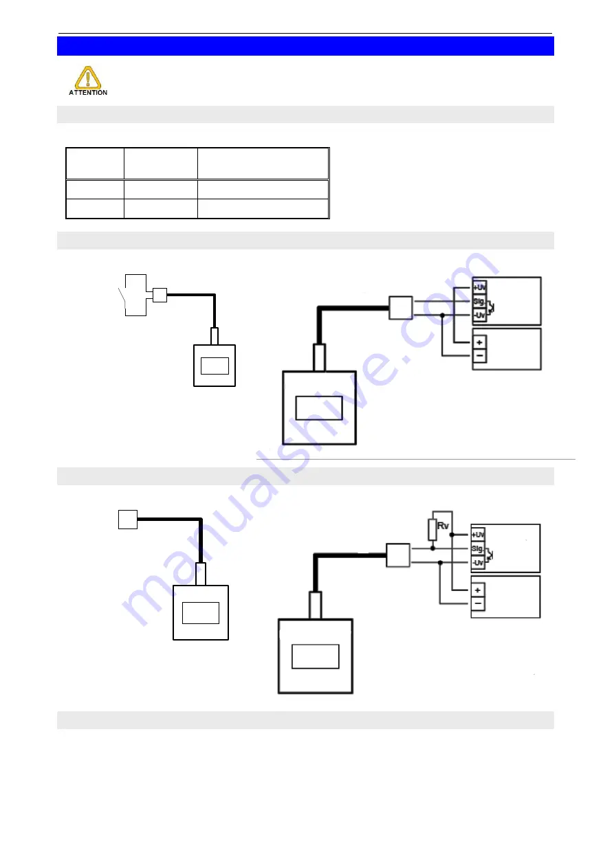
5.2 Connection an EASY
LOG
80IMP/S
(elec. Isolated switching contact)
Connecting diagram:
Example: connecting a transducer with npn-output
Switch-
ing
contact
transducer
power supply
for transducer
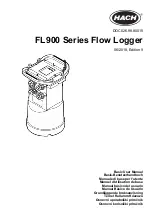
5.3 Connection an EASY
LOG
80IMP/T
(TTL-signal input, active signal)
Connecting diagram:
Example: connecting a transducer with npn-output
Signal
transducer
power supply
for transducer
Rv = (Ub_transducer
– 3 V) / 2 mA
Example: Ub = 12V => Rv = 4k5
Ub = 24V => Rv = 10k5
5.4 Connection advice
If more than
EASY
BUS
-sensor modules are connected at the same
EASY
BUS
, the input
signals of each
EASYBUS
-sensor module (e.g.
EASY
LOG
80NS
…,
EASY
LOG
80IMP,
EBN
) has to be isolated from the others.


