


BAROsense
- 7 -
V1.2
3.1
E
LECTRICAL CONNECTIONS
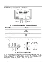
The transmitter has an internal screw terminal header.
Fig. 3.3: internal terminal header and selection jumpers
Terminal N°
Function
1
RS485 D-
2
GND
3
RS485 D+
4
Power supply positive (+Vdc)
5
GND
6
GND
7
Analog output (OUT)
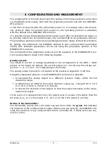
The analog output, if present, can be in current or voltage, configurable via the jump-
er to the right of the terminal header.
Fig. 3.4: analog output connection
To the left of the terminal header there is a built-in line termination that can be con-
nected or removed through a short jumper. To connect the termination, place the
short jumper between the “RT” and “CLOSE” indications. To remove the termination,
place the short jumper between the “RT” and “OPEN” indications.
Cable gland
Pressure input
Select IOUT
for current output
R
L
< (Vdc-7)/0,022
Select VOUT
for voltage output
R
L
> 10 k
Ω
Содержание DeltaOHM BAROsense
Страница 1: ...Operating manual Barometric transmitter BAROsense www deltaohm com English Keep for future reference ...
Страница 20: ...BAROsense 20 V1 2 NOTES ...
Страница 21: ...BAROsense 21 V1 2 NOTES ...
Страница 22: ...BAROsense 22 V1 2 NOTES ...
Страница 23: ......


