background image

Gfp 44TH 

October 2017 


15

12. Loading top supply roll 

1.


Slide the top supply roll onto the rear Supply unwind shaft   
a.


If using Liner-in film, the web should come off the bottom of the roll, for Liner-out 
film the web should come off the top of the roll 

2.


Position the roll in the middle of the supply shaft.     

3.


Adjust  the  brake  tension  by  turning  the  Tension  adjustment  knob                                                       
(Note: the brake tension should not prevent roll from turning) 

4.


Slide empty cardboard tube onto the top, front Liner rewind shaft


13. Threading film 

1.


Turn the Roller Gap adjustment handle to full open position to lift the upper rubber roller. 

2.


Pass the film web under the idler bar and down in front of the roller   

3.


Separate 1” of the paper liner from the film web and attach film web to a leader 
board the width of the film roll then insert leader board into the rollers 

4.


Lower the top rubber roller onto the leader board   

5.


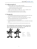
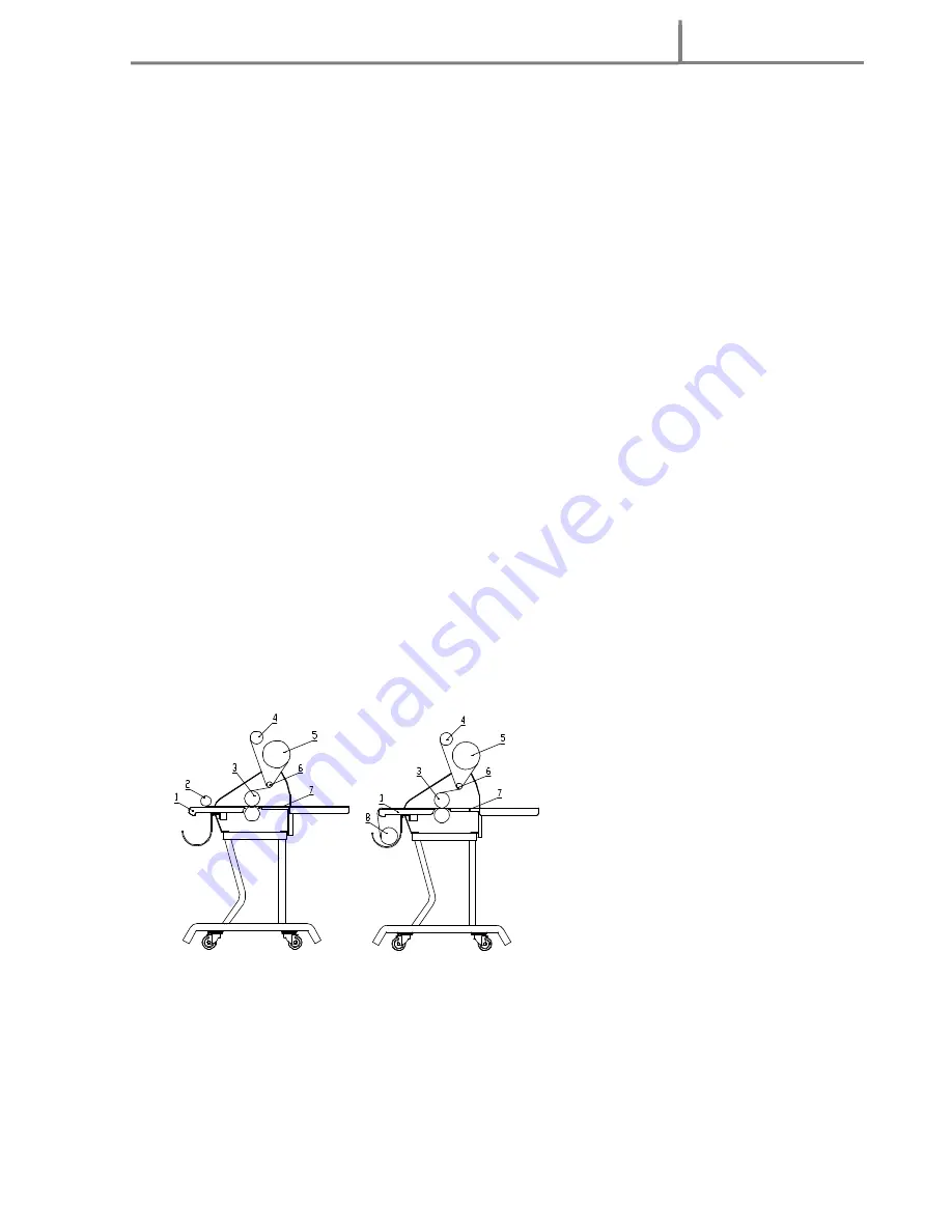
Pull the liner up and attach to a cardboard tube on the liner rewind shaft as in the diagram 
below 

6.


Use foot pedal to advance the film web until the leader board is under the roller 


Note: The film should be wrinkleless and tight to the surface of the roller. If the 
film is not tight enough, increase the roller pressure.    If wrinkles appear in the 
film web, adjust the brake tension on the top film supply roll.     


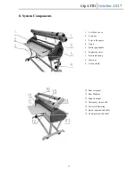
1. Feed tray                  5. PSA Film 

2. Print               

6. Idler roller   

3. Top roller                  7. Rear platform 

4. Release Liner            8. Rolled graphics 


Содержание 44TH

Страница 1: ...Gfp 44TH October 2017 0 Operating Manual 44TH Please read this manual carefully before starting operation Unpacking assembly and operating videos are available at www gfpsmoothstart com...

Страница 2: ...ar platform 9 8 System Components 12 9 Control Panel 13 10 Roller Gap Adjustment 14 11 Operation 14 12 Loading top supply roll 15 13 Threading film 15 14 Adjusting Brake Tension 16 15 Laminating Cold...

Страница 3: ...oid the user s warranty and will transfer health and safety obligations to the end user CAUTION Please pay attention to all passages with these symbols This information is vital to preventing user inj...

Страница 4: ...ckets If abnormal conditions occur switch off the power supply first Only a licensed electrician should install wiring and outlet for the laminator Do not defeat or remove electrical and mechanical sa...

Страница 5: ...r materials when cleaning the machine Do not leave the machine unattended during operations Do not mount metal materials or other hard objects Do not put burrs sharp blade or rigid materials in betwee...

Страница 6: ...ra thick and hard materials in between the rollers Do not leave objects like tools rulers knives etc on the working panels or the side cabinets to avoid their being rolled into the machine accidentall...

Страница 7: ...1 Quick Grip shafts 2 Locking Bolt 2 Stand locking screw 2 Feed Tray 1 Cardboard rewind tube 1 Allen wrench 8mm 1 Foot switch 1 Left rewind housing 14 1 Zippy knife 1 Hex screw 8mm x 80 12 Safety Shie...

Страница 8: ...olding the lid to the crate and remove the stand side frames from the top of the crate 3 Remove the cross members packed below the laminator feed tray 7b Assemble the stand 1 Assemble the stand as sho...

Страница 9: ...and orient it to the machine Stand locking wheels are to the front of the machine 2 Lift the machine and set it on the stand 3 Secure the machine to the stand using securing bolts in the accessory box...

Страница 10: ...the rear of the machine by using bolts in the accessory box 7f Attach Upper Rewind supporting brackets 1 Use the Allen head screws to affix the rewind supporting plates to the machine side frames 1 Le...

Страница 11: ...2 2 Insert slotted end of each upper shaft into the right shaft housing with tension adjustment knobs and drop shaft into place as in Figure 3 3 Rotate all outer locking sleeves to lock shafts in pla...

Страница 12: ...d with locating pin on right side frame 3 The safety shield may be rotated up for access to the rollers 7i Attach Print Hold Down Clamp 1 Rotate the safety shield up and unscrew the thumbscrews at the...

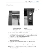
Страница 13: ...ay 3 Print roll hangers 4 Stand 5 Roller gap handle 6 Right side cover 7 Rewind housing 8 Idler bar 9 Safety shield 10 Rear exit panel 11 Rear Platform 12 Support hinges 13 Emergency stop switch 14 Le...

Страница 14: ...verse switch is used to stop rotation of the roller and switch rotation direction of the rollers 5 The green LED Ready light will illuminate when the upper roller gets to the set temperature 6 Tempera...

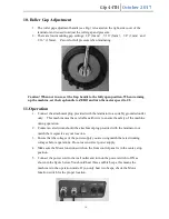
Страница 15: ...grounded outlet only This machine must have reliable earth wire to ensure the safety of the machine during operation 2 Contact an electrician should the attachment plug provided with the laminator no...

Страница 16: ...ller 2 Pass the film web under the idler bar and down in front of the roller 3 Separate 1 of the paper liner from the film web and attach film web to a leader board the width of the film roll then ins...

Страница 17: ...e width or wider than the film supply roll To clean the rollers use rubber eraser or Isopropyl Alcohol and a lint free cloth 15a Single sheets or media from a roll 1 Load a roll of laminating film on...

Страница 18: ...e foot pedal to advance the film web half way through the roller and stop 9 Position print on the sled and insert into rollers 10 Depress the foot switch and run sled through 11 Insert another leader...

Страница 19: ...rst board to keep the film adhesive from touching the bottom roller 17 Laminating pouches 1 The recommended temperature setting is 10 on Temp dial 302 F 2 The recommended speed setting is 1 Note If th...

Страница 20: ...ttach vinyl web to a leader board 8 Use foot pedal to advance the leader board half way through the roller and stop 9 Insert mounting board to be coated and depress foot switch 10 After the last board...

Страница 21: ...2 During normal operation of the machine the buzzer gives two sounds and the power indicator flickers In this case it shows that temperature detected by the temperature sensor on the upper roller is...

Страница 22: ...position then back to ON and allow the ready light to come on 22 Photo Safety Eye 1 When the machine switch is set to FWD it is possible to normally adjust speed of the machine If the photo safety eye...

Страница 23: ...m adhesion or cloudy prints 1 Nip roller pressure too low 2 Dust on the surface of the print 3 Not hot enough if using thermal film 1 Increase nip roller pressure 2 Clean print surface before laminati...

Страница 24: ...Pressure settings 0 1 16 1 8 3 16 and 1 4 respectively Maximum gap height 5 16 Rated input voltage 120 V 60 Hz Maximum input power 1440 W Maximum input current 12 A Dimensions w rear deck up L W H 57...

Страница 25: ...ty made herein is in lieu of all other warranties expressed or implied including any warranty or merchantability or fitness for a particular purpose Gfp will not be liable for personal damage or perso...

Отзывы: