


IQ lock AUT, EL / EL DL, EM / EM DL, C / C DL, M / M DL
6
Your contribution to environmental protection
In order to interrupt this electrical activation in case of a fire, permissible fire alarms with trigger mechanisms, in
accordance with the DIBt Directive, must be employed for hold-open systems.
When motor locks are used on fire and smoke protection doors, three different installation situations can occur.
The following chapters must be heeded in this case.
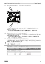
1.7.1 Release via on-site fire alarm system
Connection of an on-site fire alarm system (BMA) to the motor lock control (MST 210).
This connection is implemented via the “smoke detector” input especially provided. A zero-potential or non-
isolated contact is required by the BMA for this.
The planning of the installation of the smoke detectors is implemented on site. It should be pointed out that
when motor locks are used, smoke detectors in accordance with the above-mentioned directive must be fitted.
Smoke development on both sides of the door must be detected by the BMA.
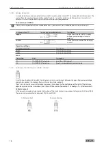
1.7.2 Release via trigger mechanism of hold-open systems
In accordance with the DIBt Directive for hold-open systems, the following is necessary, taking account of the
difference for the use of the “permanently unlocked” and “secured by day” modes described:
Ceiling height above lintel lower edge ≤ 1 m
2 ceiling-mounted detectors are required
Deviation from DIBt Directive:
The installation of only one lintel-mounted detector is not authorised in this case, since the fire can only be
detected on one side if the door is closed.
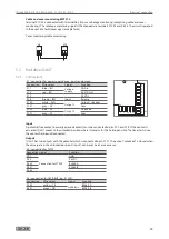
Ceiling height above lintel lower edge > 1 m
2 ceiling-mounted detectors and 1 lintel-mounted detector are required This corresponds to 2 ceiling-mounted
detectors and 1 smoke switch control unit.
The smoke switch control unit (RSZ 5 and RSZ 6, includes power 1 lintel-mounted detector) is connected
directly to the MST in accordance with wiring diagram.
1.7.3 Motor lock in “night” mode of operation
The motor lock is used in “night” mode of operation only. In the “night” mode of operation, the automatic
crossbar projection of 20 mm is implemented every time the door is closed. The GEZE SecuLogic access control,
for example, regulates controlled admission. In this case, the crossbar is retracted and the door can be passed
through against the direction of emergency exit.
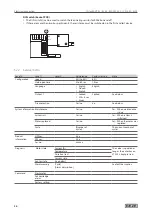
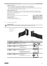
With the motor lock control MST 210, different release times can be set using a DIP switch.
Setting of the release time
Opening time “x” = 1 s
Setting options for release time:
Switch
Switch position Release time
1
ON
x + 1 s
2
ON
(x) + 2 s
3
ON
(x) + 5 s
4
ON
(x) + 10 s
Example:
Set release time = 9 s
In order to ensure that the lock locks itself mechanically, the hold-open time must not exceed 4 seconds. For this
reason only switches 1 and 2 may be active in case of the DIP switch.
2
Your contribution to environmental protection
à
When disposing of the self-locking panic locks, separate the different materials and have them recycled.
à
Legal regulations must be observed during the disposal of self-locking panic locks.
à
GEZE self-locking panic locks are certified with the Environmental Product Declaration according to ISO
14025 from the Institut Bauen und Umwelt e.V. (
Institute for Construction and the Environment
). This approval
describes the specific environmental performance of the IQ locks and confirms that the GEZE lock family
promotes environmentally friendly and healthy construction work.
Содержание IQ lock AUT
Страница 56: ...IQ lock AUT EL EL DL EM EM DL C C DL M M DL 56 Wiring diagrams ...
Страница 66: ...IQ lock AUT EL EL DL EM EM DL C C DL M M DL 66 Annex ...
Страница 68: ...IQ lock AUT EL EL DL EM EM DL C C DL M M DL 68 Annex ...
Страница 70: ...IQ lock AUT EL EL DL EM EM DL C C DL M M DL 70 Annex ...
Страница 71: ...IQ lock AUT EL EL DL EM EM DL C C DL M M DL 71 Annex ...


