background image

16

INSTALLATION INSTRUCTIONS

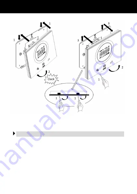
Coupling

Release

Figure B shows a diagram of the electrical connections.
Connect the power supply, and connect any inputs and the output contact to the screw
terminals on the back of the thermostat (figure A).

Electric connections
Содержание GW 16 971CB

Страница 1: ...to ICE da incasso ICE thermostat flush mounting Thermostat ICE encastrer Termostato ICE de empotrar ICE Thermostat f r den Unterputz MANUALE DI INSTALLAZIONE INSTALLATION MANUAL MANUEL D INSTALLATION...

Страница 2: ...iaire pour contact sans potentiel Entrada auxiliar para contacto libre de potencial Zusatzeingang f r potentialfreien Kontakt 2 1 3 4 5 Ingresso per sensore di temperatura esterna Input for outdoor te...

Страница 3: ...CRIZIONE GENERALE In breve 5 Elementi di comando e visualizzazione 6 Descrizione comandi 6 ISTRUZIONI D INSTALLAZIONE Corretto posizionamento 7 Montaggio 7 Connessioni elettriche 8 ISTRUZIONI D IMPIEG...

Страница 4: ...ria una protezione speciale contro la penetrazione di acqua L organizzazione di vendita GEWISS a disposizione per chiarimenti e informazioni tecniche Attenzione seguire le regole per la corretta insta...

Страница 5: ...temperature di regolazione per il raffrescamento Teconomy Tprecomfort Tcomfort Tprotezione_alte_temperature 2 tipi di controllo modalit HVAC o Setpoint algoritmi di controllo per impianti a 2 vie 2 pu...

Страница 6: ...che illumina l area di scorrimento assume colore diverso durante la fase di attivazione del riscaldamento raffrescamento o in base alla funzione svolta dal parametro in corso di modifica rosso per il...

Страница 7: ...cino a porte o finestre accanto a termosifoni o condizionatori e non deve essere colpito da correnti d aria e dall illuminazione solare diretta Corretto posizionamento Montaggio Il montaggio del termo...

Страница 8: ...Aggancio Sgancio La figura B mostra lo schema delle connessioni elettriche Collegare l alimentazione gli eventuali ingressi e il contatto d uscita ai morsetti a vite posti sul retro del termostato fig...

Страница 9: ...splay per consentire la pulizia della placca in vetro senza che vengano effettuate delle modifiche involontariamente La funzione attivabile disattivabile secondo la procedura seguente Abilitazione toc...

Страница 10: ...mperatura integrato intervallo di regolazione 5 C 40 C intervallo di misura 0 C 60 C risoluzione di misura 0 1 C accuratezza di misura 0 5 C tra 10 C e 30 C Intervalli di regolazione temperature T ant...

Страница 11: ...PTION Briefly 13 Command and display elements 14 Description of the commands 14 INSTALLATION INSTRUCTIONS Correct positioning 15 Assembly 15 Electric connections 16 USER INSTRUCTIONS Behaviour upon th...

Страница 12: ...uirements for household devices set out by the national standards and rules applicable to low voltage electrical installations which are in force in the country where the products are installed or whe...

Страница 13: ...antigelo Tanti freeze 4 cooling adjustment temperatures Teconomy Tprecomfort Tcomfort Tprotection_high_ temperatures 2 types of control HVAC or Setpoint control algorithms for 2 way systems 2 ON OFF p...

Страница 14: ...er The circular light guide that illuminates the sliding area which changes colour during the heating cooling activation phase or based on the function performed by the parameter being modified red fo...

Страница 15: ...es near doors or windows or next to ra diators or air conditioning units and it must not be in the line of draughts or direct sunlight Correct positioning Assembly The thermostat can be assembled on a...

Страница 16: ...S Coupling Release Figure B shows a diagram of the electrical connections Connect the power supply and connect any inputs and the output contact to the screw terminals on the back of the thermostat fi...

Страница 17: ...N This function makes it possible to temporarily inhibit the display so the glass plate can be cleaned without making any unintentional modifications The function can be enabled disabled as follows En...

Страница 18: ...ture sensor adjustment range 5 C 40 C measurement range 0 C 60 C measurement resolution 0 1 C measurement accuracy 0 5 C between 10 C and 30 C Temperature adjustment range T anti freeze 2 7 C T high t...

Страница 19: ...En synth se 21 l ments de commande et de visualisation 22 Description des commandes 22 CONSIGNES D INSTALLATION Positionnement correct 23 Montage 23 Connexions lectriques 24 CONSIGNES D UTILISATION C...

Страница 20: ...latives aux appareils usages domestiques et analogues pr vues par les normes et r gles nationales applicables aux installations lectriques basse tension en vigueur dans le pays o les produits sont ins...

Страница 21: ...fort Tcomfort Tantigel 4 temp ratures de r glage de la climatisation Teconomy Tprecomfort Tcomfort Tprotection contre les hautes temp ratures 2 types de contr le modalit HVAC ou par point de consigne...

Страница 22: ...laire clairant la zone de d filement prend une couleur diff rente lors de la phase d activation du chauffage et de la climatisation ou bien selon la fonction ex cut e par le param tre en cours de modi...

Страница 23: ...e pr s d un radiateur ou d un climatiseur et il ne doit pas se trouver dans un courant d air ou la lumi re directe du soleil Positionnement correct Montage Le montage du thermostat peut s effectuer au...

Страница 24: ...crochage D crochage La figure B reporte le sch ma des connexions lectriques Raccorder l alimentation les ventuelles entr es et le contact de sortie aux bornes vis mont es sur l arri re du thermostat f...

Страница 25: ...t d inhiber temporairement l afficheur afin de nettoyer la plaque en verre sans risque d effectuer une modification involontaire La fonction peut tre activ e ou d sactiv e selon la proc dure suivante...

Страница 26: ...gr intervalle de r glage 5 C 40 C Intervalle de mesure 0 C 60 C r solution de la mesure 0 1 C pr cision de la mesure 0 5 C entre 10 C et 30 C Intervalles de r glage de la temp rature T antigel 2 7 C T...

Страница 27: ...En s ntesis 29 Elementos de mando y visualizaci n 30 Descripci n mandos 30 INSTRUCCIONES DE INSTALACI N Colocaci n correcta 31 Montaje 31 Conexiones el ctricas 32 INSTRUCCIONES DE USO Comportamiento...

Страница 28: ...os para los aparatos para uso dom stico dictados por las normas y los reglamentos nacionales aplicables a las instalaciones el ctricas de baja tensi n vigentes en el pa s donde se instalan los product...

Страница 29: ...hielo 4 temperaturas de regulaci n para la refrigeraci n Teconomy Tprecomfort Tcomfort Tprotezione_alte_temperature Tprotecci n_altas_temperaturas 2 tipos de control modo HVAC o Setpoint algoritmos de...

Страница 30: ...que ilumina el rea deslizante adopta un color distinto durante la fase de activaci n de la calefacci n refrigeraci n o seg n la funci n realizada por el par metro que se est modificando rojo para la...

Страница 31: ...de puertas o ventanas al lado de ter mosifones o aires acondicionados y no debe recibir corrientes de aire ni la iluminaci n directa del sol Colocaci n correcta Montaje El montaje del termostato pued...

Страница 32: ...esenganche La figura B muestra el esquema de conexiones el ctricas Conectar la alimentaci n las entradas que hubiera y el contacto de salida a los bornes de tornillo situados en la parte posterior del...

Страница 33: ...bir temporalmente la pantalla para poder limpiar la placa de cristal y evitar efectuar cambios accidentales La funci n se puede activar desactivar seg n el procedimiento siguiente Habilitaci n tocar s...

Страница 34: ...integrado intervalo de regulaci n 5 C 40 C intervalo de medida 0 C 60 C resoluci n de medida 0 1 C precisi n de medida 0 5 C entre 10 C y 30 C Intervalos de regulaci n de temperaturas T antihielo 2 7...

Страница 35: ...REIBUNG Kurzbeschreibung 37 Elemente f r Steuerung und Ansicht 38 Beschreibung der Steuerungen 38 INSTALLATIONSANWEISUNGEN Korrekte Positionierung 39 Montage 39 Elektrische Anschl sse 40 GEBRAUCHSANWE...

Страница 36: ...en f r Haushaltsger te installiert werden die durch im Installationsland geltenden Normen und Bestimmungen f r Niederspannungsanlagen geregelt werden Falls solche nicht vorgesehen sind muss man die in...

Страница 37: ...TComfort Tprotezione_alte_ temperature TSchutz_vor_hohen_Temperaturen 2 Steuertypen Modus HVAC oder Sollwert Regelalgorithmen f r 2 Rohranlagen 2 ON OFF Punkte oder proportionale PI Regelung mit PWM S...

Страница 38: ...Parameter zugeordnet werden soll Die runde Lichtf hrung die den Gleitbereich beleuchtet nimmt w hrend der Aktivierungsphase der Heizung K hlung oder je nach ausge bter Funktion des gerade in nderung b...

Страница 39: ...zk rpern oder Klimager ten installiert werden und es darf keinen Luftstr men oder direkter Sonnenbestrahlung ausge setzt werden Korrekte Positionierung Montage Die Montage des Thermostats kann sowohl...

Страница 40: ...stigung Ausklinken Die Abbildung B zeigt den elektrischen Anschlussplan Die Versorgung die eventuellen Eing nge und den Ausgangskontakt an die Schraubklemmen auf der R ckseite des Thermostats anschlie...

Страница 41: ...das Display vor bergehend deaktivieren um die Reinigung des Abdeckrahmens aus Glas zu erm glichen ohne dass unabsichtlich nderungen durchgef hrt werden Die Funktion ist wie folgt aktivierbar deaktivi...

Страница 42: ...Messelemente 1 integrierter Temperaturf hler Regelintervall 5 C 40 C Messintervall 0 C 60 C Messaufl sung 0 1 C Messgenauigkeit 0 5 C zwischen 10 C und 30 C Temperaturregelintervalle T Frostschutz 2 7...

Страница 43: ......

Страница 44: ...2 della Direttiva Europea 2004 108 CE si informa che responsabile dell immissione del prodotto sul mercato Comunitario According to article 9 paragraph 2 of the European Directive 2004 108 EC the res...

Отзывы: