9.2.1.2
P
AD
C
OMPONENTS
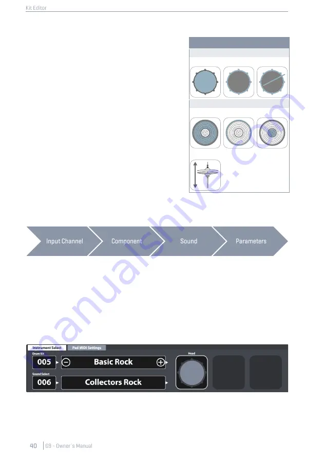
The pad component icons are located on the right-hand
side of module 2. You can tap on an icon to activate the
component, giving access to its parameters in module 3.
The appearance of the icons and their naming depends
on the
Trigger Bank
assigned. Assigning a cymbal trigger
bank will display Bow/Bell/Edge icons and cymbal pa-
rameters in module 3, even though the corresponding
input channel is labeled as e.g. Snare. This means in most
cases you can convert a pad input channel to a cymbal
input and vice versa. However, not all components of the
trigger bank might be accessible due to a different
hardware design of the channel on the trigger board.
When gaining an understanding of the G9 Kit Editor, it is
important to point out that all function sets and parame-
ters of module 3 and 4 always refer to the selected pad
under
Input Channels
and its active
Component
(com-
ponent icon in module 2). The sound assigned to a com-
ponent is shown in the
[Sound Select]
field. Sound name
and component icon frames use the same
color values
,
giving a quick visual feedback about which component
is active. By changing either pad or component, sounds
(module 2) and parameter values (module 3) will update accordingly.
To keep track of your sound settings, try to look at this mode as a cascade of Input Channel, Com-
ponent, Sound and Parameters:
Every edit of sounds should follow the order shown above.
9.2.1.3
S
OUND
S
ELECT
The
Sound Select field
displays the sound assigned to the active pad component of the active pad
(Input Channel). Sound names are highlighted in the color of the active component tile to help the
understanding of the connection between icon and sound name visible.
With the correct component selected, tap the
[Sound Select name]
field to open the
Sound Browser
and select a new sound from the sound library by double tapping on a list entry.
•
Module 1
•
Module 2
•
Module 2
•
Module 3/4
Pad Component Icons
Drums
Head
Rim
X-Stick
Cymbals
Bow
Edge
Bell
Hi-Hat
Содержание G9
Страница 1: ...CONTENT ...
Страница 2: ......
Страница 3: ......
Страница 4: ......
Страница 5: ......
Страница 6: ......
Страница 7: ......
Страница 8: ......
Страница 9: ......
Страница 10: ......
Страница 20: ...3 ASSEMBLY INSTRUCTIONS 3 1 MOUNT BRACKET ASSEMBLY 3 2 CONNECT YOUR EQUIPMENT TO THE CONSOLE 3 2 1 FRONT PANEL ...
Страница 21: ...3 2 2 REAR PANEL Make sure the power is OFF when connecting the drum module with external devices ...
Страница 46: ......
Страница 70: ......
Страница 86: ......
Страница 97: ...The following table lists all parameters available by component ...
Страница 114: ......
Страница 176: ......


