8
Actions in the event of an alarm
1.
Proceed immediately to fresh air, outdoors or to an open window or door.
2.
Call the fire brigade.
3.
Do not re-enter the affected area, or remain at the open window/door.
4.
Await the arrival of the fire brigade.
5.
Fully ventilate all rooms.
6.
If the danger is no longer present, the CO detector automatically resets and returns to
its normal state.
Displays and functions (fig. 7)
1.
Test/Silence
button. This button is used to check the functionality or to silence the alarm.
2.
Speaker opening.
3.
POWER
display (green LED signal). Signals that the device is ready for use with constant flashing at
30-second intervals.
4.
ERROR
display (yellow LED signal). The error display shows malfunctions or warnings regarding
CO detection.
5.
ALARM
display (red LED signal). If CO is detected, the red LED lights up.
Installation
Recommendation for maximum safety:
Install one CO detector in each child‘s room and bedroom, in all
rooms with gas heating, stoves/ovens or fireplaces as well as in the hallways on each floor and in the garage.
Minimum recommended level of protection:
Install one CO detector in each hallway and in rooms with
gas heating, stoves/ovens or fireplaces.
Installation position (figs. 1-4)
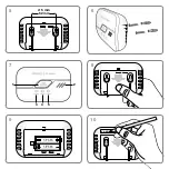
Install or place the alarm as centrally as possible on a clear surface and near to potential sources of danger
(e.g. gas heaters). If installing on a wall, the minimum distance from the floor should be no less than 1.5 m,
and the minimum distance from the ceiling should be no less than 0.2 m.
Installation and commissioning
1.
The CO alarm can be operated in the following two varying manners:
Wall installation, or standing on a suitable base.
Follow the steps below in the specified order to install the alarm on the wall. Use a spirit level to mark the
drill holes in a horizontal position. (Distance 52 mm —
see fig. 5)
2.
Drill the holes in the previously marked position using a suitable drill. (Drill diameter Ø 5 mm) Ensure that
you do not damage any wires.
3.
Push the wall plugs into the drill holes and screw in the two supplied screws until the screw heads are
only protruding by approximately 5 mm.
4.
Open the battery compartment on the rear of the device by pressing on the hatched arrow marking and
pushing the cover in the direction of the arrow
(fig. 8)
.
5.
Insert the two 1.5 AA batteries into the battery compartment, ensuring that the polarity is correct.
The
battery compartment has a safety mechanism:
If batteries are not inserted, the battery compartment
cover cannot be closed. As soon as the batteries are inserted correctly the device confirms this with a
signal tone, and all three front LEDs briefly light up. The device is ready to use and initially switches to a
calibration phase. During the first 30 seconds of the calibration phase, the green „
POWER
“ LED flashes
briefly approximately every three seconds. After this, the device moves into the operating phase (the green
„
POWER
“ LED lights up once every 30 seconds).
6.
Enter the installation date on the supplied sticker as soon as possible
(fig. 10)
.
7.
The back case of the alarm can now be placed on the screws and clicked into place or set down in the
desired position. Note the instructions in
figs. 1-4
.
9
GB
FR
IT
PL
DE
SK
SL
CZ
Содержание FlammEx FMG 4313
Страница 1: ...FMG 4313 04313 ...
Страница 2: ...1 2 3 4 50 C 20 C ...
Страница 3: ...9 10 5 6 7 8 3 4 5 2 1 xx xx 52 mm Ø 5 mm ...
Страница 36: ...36 ...
Страница 37: ...37 ...


