19
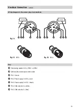
Wiring diagram for the sensor plug-in connections
Fig. 14
v
t
w
w
t
u
u
v
r
r
Electrical Connection
– continued –
Fig. 15
RES 1
Fig. 16
RES 2
r
Terminating resistor 120 Ω, RES 1 or RES 2
s
CAN bus line, twisted pair control cable
t
Pin 1: Screen
u
Pin 2: Power supply 24 V DC+ (red)
v
Pin 3: Power supply 24 V DC– (black)
w
Pin 4: CAN data line C
H
(white)
x
Pin 5: CAN data line C
L
(blue)
Key
x
x
120 Ω
120 Ω
Содержание NRG 16-41
Страница 27: ...27 For your Notes ...


