background image

5

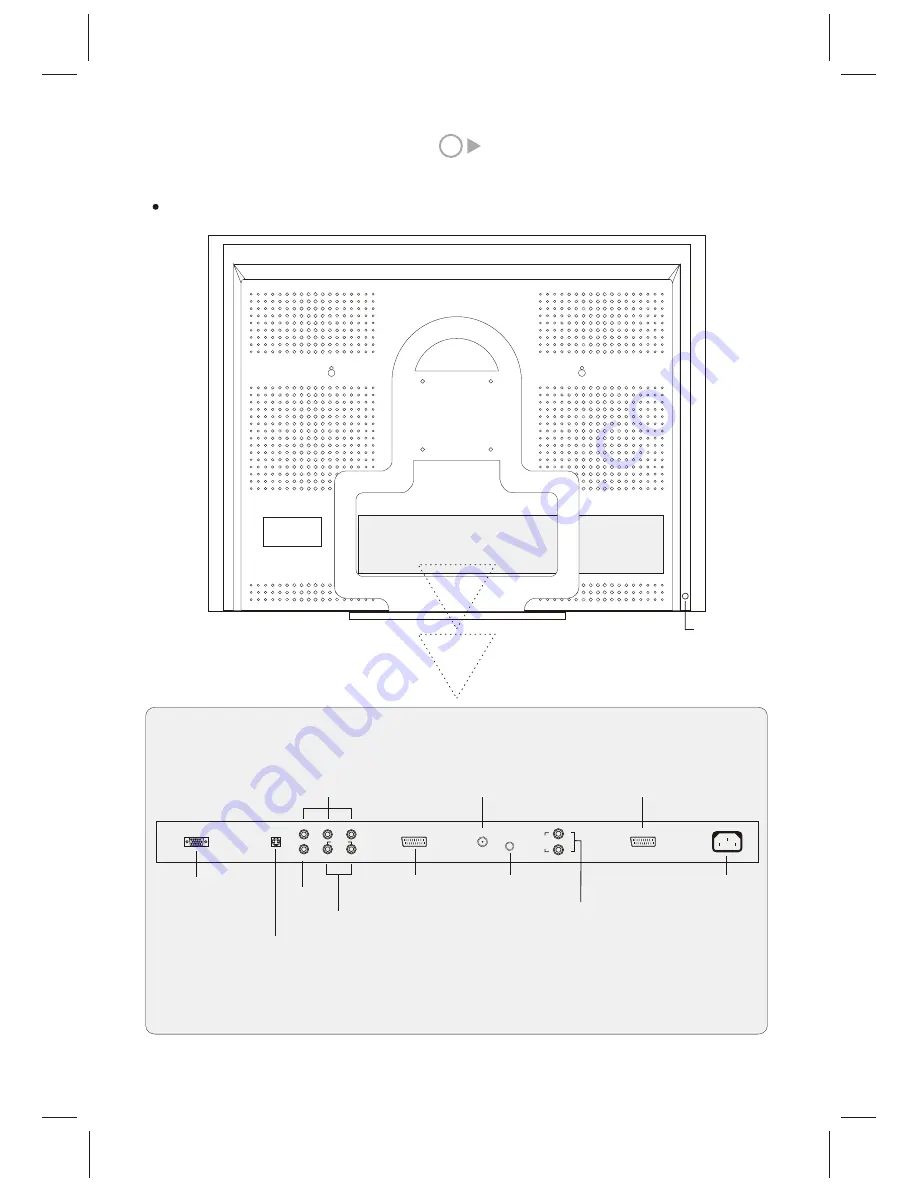
Rear view

Power Switch

PC IN

S-VIDEO

R

L

VIDEO 1

Y

Pb/Cb

Pr/Cr

AUDIO

SCART 

 PC AUDIO 

AIR/CABLE

PC Input

SCART Input/Output
        (Decoder)

S-Video Input

Component Video Input/HD Video Input

Antenna Input

Video Input1

Audio Input

PC Input

AC IN

R

L

AUDIO

OUT

Power Input

Audio Out 

SCART2 

SCART 2Input/Output
        (Decoder)

Содержание GTV3203

Страница 1: ...Operating Instructions 32 LCD DISPLAY...

Страница 2: ...gram VI Mount up the base VII Connection for external video and audio equipment VIII Preparation for switch on IX Basic operation X How to adjust the imageeffect XI How to adjustthe sound effect XII T...

Страница 3: ...ower and remove the antenna connection to avoid the damage to this unit In case the remote control is not used for a long period of time take out the batteries to avoid liquid leakage I Main features...

Страница 4: ...al 1366 768 16 9 160 240V AC 50 60Hz 48 25MHz 168 25MHz PALB G I D K SECAM L B G D K YPbPr 480p 576p 720p 1080i YCbCr 480i 576i HDTV support format is in the attached table VGA thesupporting format is...

Страница 5: ...ignal Stand by On Exit menu Select the previousmenu item Select the nextmenu item Select the submenuof current item Confirmation Confirmation Decrease the valueof the current item The operation situat...

Страница 6: ...b Cb Pr Cr AUDIO SCART PC AUDIO AIR CABLE PC Input SCART Input Output Decoder S Video Input Component Video Input HD Video Input Antenna Input Video Input1 Audio Input PC Input AC IN R L AUDIO OUT Pow...

Страница 7: ...show on fig 1 The TVand the connectingface of thebase can berotated together o 3 Stand the TV with the base onthe table Itcan be rotatedclockwise and counterclockwise up to15 4 When the redline in the...

Страница 8: ...ources and inputs of the unit correspondingly Make sure of good contact All connection and disconnection can only be done under off status The computer can only be switched on after switching on the e...

Страница 9: ...T ERASE SKIP INSERT REPLACE Stand by On Channel information display Time display TIME menu shouldbe set atfirst MUTE On Off TV AV Scart AV 1 AV 2 S Video Component Analog RGB Sleep time setting Shortc...

Страница 10: ...ge 4 or contact the Service centre IX Basic operation 2 Select thereceiving signal inputstatus Press the TV AV button And themenu will appear Select the desirablesignal by pressingP or P Press MENU to...

Страница 11: ...s V or V button to adjust program number Press P or P button to select BAND item Press V or V button to select V UHF or CABLE Press P or P button to select CHANNEL item Press V V or digital button to...

Страница 12: ...the value or select the status SOUND VOLUME BALANCE SOUND MODE 20 0 AVC Off NO DATA 100 100 100 100 6 How to use the functionof teletext Start up Press TEXT button on the remote controller andthe imag...

Страница 13: ...SHEET OSD POSITION FILM MODE Fill Screen Opaque Video OSD LANGUAGE English When the signal input status is AV Scart AV1 A 2 S Video the menu is m instead of k Note SOUND VOLUME BALANCE SOUND MODE 20 0...

Страница 14: ...same function TIME SLEEP WAKE UP TIME Off WAKE UP Off LEFT RIGHT EXIT Press P or P button to select WAKE UP item Then press button to confirm Image q will appear on the screen Press V or V button to s...

Страница 15: ...itemin menu s thenpress MENU button to confirm the menu u willappear on thescreen Press P or P button toselect the item then press V or V button to increaseor decrease the value of theitem H POSITION...

Страница 16: ...N SOURCE PIP off TV PIP XIX Troubleshooting If there isany abnormal situationduring the operation please make thecorresponding check accordingto the following instruction beforesending it forrepair No...

Страница 17: ...The image hasno color The remote controllerdoes not work Check if there is any obstacle between the transmission window of the remote controller and the Remote sensor of this unit Although the image...

Страница 18: ...SPW2 025 347 SS...

Отзывы: