GeoVision GV- DFR1352 Скачать руководство пользователя страница 3


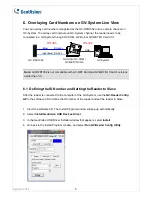
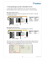
5.1  Connecting through Wiegand Interface 

Up to eight GV-DFR1352 readers can be connected to GV-AS810 Controller through the 
controller’s Wiegand interface. 

Wire Color


Function


Black GND 
White  

Wiegand Data 1 

Green 

Wiegand Data 0 


Red DC 

12V 


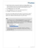
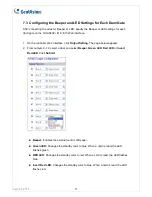
5.2  Connecting through RS-485 Interface 

Up to eight GV-DFR1352 readers can be connected together to the RS-485 interface on GV-
AS810 Controller.  


Connecting four or less readers to GV-AS810 Controller:  

Wire Color


Function

Black GND 
Light Blue 

RS-485 -

Blue RS-485 

+

Red DC 

12V 

RS

485


April 24, 2014 


3


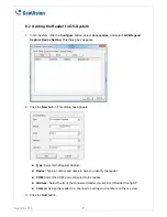
Connecting five or more readers to GV-AS810 Controller:  

For readers five to eight, connect the RS-485 cable to the RS-485 interface on GV-
AS810 and then connect the 12V power output and GND of the reader to a 12V power 
output on the controller.   

RS4

8

5

12

V

 O

U

TP

U

T


Содержание GV- DFR1352

Страница 1: ...ealed and IP66 compliant housing for outdoor use 1 Packing List 1 GV DFR1352 Card Reader 2 Screw x 2 3 Screw Anchor x 2 4 Front Cover Plate x 2 5 GV DFR1352 Software CD Front View 2 Installation Insta...

Страница 2: ...of LED and Beeper to be defined by the GV AS400 410 810 For details on how to configure the settings refer to 7 Enabling External Control of the Beeper and LED later in this installation guide 5 Conne...

Страница 3: ...FR1352 readers can be connected together to the RS 485 interface on GV AS810 Controller Connecting four or less readers to GV AS810 Controller Wire Color Function Black GND Light Blue RS 485 Blue RS 4...

Страница 4: ...e GV AS210 Web interface click Extended Reader This dialog box appears 2 In the GV Reader CR420 GF1921 GF1922 section select the RS485 checkbox in front of the ID number and type the Serial Number on...

Страница 5: ...mpatible with GV NET Card and GV NET IO Card of versions earlier than V3 6 1 Defining the ID Number and Setting the Reader to Slave After the reader is connected to the computer of the GV System use t...

Страница 6: ...you need to set up a unique ID number for each reader For this you need to connect each reader to the computer one reader at a time and follow the instructions above to set up an ID number Note 1 If t...

Страница 7: ...he New button This dialog box appears Type Select GV Wiegand Capture Device Type a number and name to help you identify the reader COM Select the COM port connected to the reader Address Select the ID...

Страница 8: ...o GV AS400 410 810 3 Specify the Beeper and LED settings for each door through the Web interface of GV AS400 410 810 7 1 Setting up Beeper and LED on GV Reader Config AP To enable the external control...

Страница 9: ...e drop down list 6 Select an ID number for the reader Make sure the ID number on the GV Reader Config AP matches the ID number set on the Extended Reader page of the GV AS400 410 810 Web interface 7 C...

Страница 10: ...use the light red wire instead Wire Color Function Black GND Orange Green LED Light Red Red LED Wiring Beeper to GV AS Controller The diagram below shows the connection for wiring the beeper on GV AS...

Страница 11: ...tting The page below appears 2 From outputs 9 12 select a door and select Beeper Green LED Red LED or Invert Red LED Click Submit Beeper Enables the external control of Beeper Green LED Changes the st...

Страница 12: ...tes after the firmware is updated WARNING The interruption of power supply during updating causes not only update failures but also damages to the device In this case please contact your sales represe...

Страница 13: ...Color Black Operating Temperature 30 C 65 C 22 F 149 F Operating Humidity 10 90 no condensation Dimensions W x H x D 20 9 x 10⁵ 6 x 20 5 mm 0 8 x 4 2 x 0 8 in Weight 80 g 0 17 lb Ingress Protection IP...

Отзывы: