


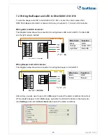


7.2 Wiring the Beeper and LED to GV-AS400 / 410 / 810
To wire the beeper and LED to GV-AS400 / 410 / 810, connect the control wires of GV-
DFR1352’s Beeper, Red LED or Green LED to any of outputs 9 ~ 16 on GV-AS Controller.
Wiring LED to GV-AS Controller
The diagram below shows the connection for wiring Green LED on GV-AS810. For Red LED,
use the light red wire instead.
Wire Color
Function
Black GND
Orange Green
LED
Light Red
Red LED
Wiring Beeper to GV-AS Controller
The diagram below shows the connection for wiring the beeper on GV-AS810.
Wire Color
Function
Black GND
Yellow
Beeper
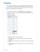
After wiring, you also need to go to GV-ASManager to select the alarm conditions that will set
off the reader’s beeper. In GV-ASManager, right-click the GV-AS Controller in the device list,
click
Settings
, and click the
Door / Gate
tab to select the alarm conditions.
April 24, 2014
10