User Manual - P series
20
www.georgin.com
VI.
Wiring
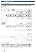
1. The electrical switch
Resting state of the switch(es) :
At rest, contact is established between C-NC.
According to the type of action (opening or
closing of the electrical circuit), make the electrical
connection on the terminal block between C-NC
or C-NO.
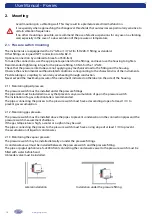
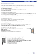
2. Cable inlets
The instruments (except explosion-proof housings) are supplied with one or two M20 cable glands
For Ø 7.5 to 13 mm cable (standard instrument)
For Ø 8 to 13 mm cable (S.I. and Ex de instrument)
Other cable gland models are available on request.
The instrument can also be supplied without cable inlets. In that case, the instrument is supplied with an
M20 thread as standard. The cable gland must be mounted according to the attached datasheet.
Explosion-proof housings: the housing is supplied as standard with a type 3/4"NPT cable inlet. Cable
glands are available as an option. The choice of cable gland directly affects the certification, and could lead
to the equipment being declassified. Refer to the ATEX instruction sheet. The cable gland must be mounted
according to the attached datasheet. Apply graphite grease on the cable entry threading before tightening
the cable gland.
Ensure that the cable gland has been tightened sufficiently, and add 'drip protection' to the cable in order to
preserve the instrument's IP level.
3.
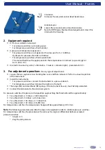
Internal terminal blocks
The terminal blocks are designed for the following maximum wire size: 2.5 mm² for standard models and 1.5 mm² for
ATEX models.
Contact No.2
Contact No.1
NC
C
NO
NC
C
NO
Standard contacts
4 / 6 / 8 / 10 / 16 / 20 (D) (T)
•
•
•
blue
red
white
34 / 54 / 38 / 58 (D) (T)
blue
red
white
blue
red
white
18 (D)
•
•
•
white
red
blue
Nitrogen sealed contacts
96 / 98
•
•
•
red
white
green
106 / 116 / 108 / 118
red
white
green
red
white
green
Explosion-proof contacts
60 (D)
•
•
•
4
1
2
160 / 170 (D)
4
1
2
4
1
2
62 (D)
•
•
•
2
1
4
162 / 172 (D)
2
1
4
2
1
4
Cable outlet explosion-proof contacts
60C
•
•
•
brown
white
green
160C / 170C
brown
white
green
brown
white
green
62C
•
•
•
grey
black
brown
162C / 172C
grey
black
brown
grey
black
brown
For specific electrical connections, refer to the associated technical drawings.
Housing closure (except explosion-proof housings) :
To preserve the instrument's ingress protection (IP) index, the cover must be closed and tightened to the
following torque: 1.2 N∙m.
NC
Position above the threshold
Position below the threshold
C
NO

