User Manual - P series
17
www.georgin.com
5.2. Procedure B2: Diaphragm-actuated differential instrument
For reasons related to production and metrology, low- and medium-pressure differential instruments are adjusted
relative to each other, with the LP chamber vented to atmosphere.
The procedure is identical to the procedure described in the previous point (B.1. Single instrument).
The HP chamber is connected to the pressure bench, and the LP remains at atmospheric pressure.
5.3. Procedure B3: Bellows-actuated differential instrument
Example: Set the low threshold to 1 bar downwards and the high threshold to 3 bar upwards, and static pressure 10
bar.
5.3.1. Setting the lower threshold
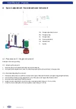
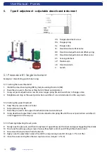
1. Inhibit the dead band spring (RE) by fully loosening the knob (ME).
2. Go up to the desired static pressure in both chambers (10 bar), and stabilise.
3. Isolate both chambers.
4. Create a pressure differential in favour of the HP chamber equal to the desired low threshold value “1 bar“
(e.g., HP=1 bar, LP=9 bar).
5. Using set point adjustment screw VG, relax range spring RG until the exact point when switch(es) C is/are
triggered on the way up.
6. Retighten and stop at the exact point where switch(es) C is/are interlocked on the way down.
5.3.2. Setting the upper threshold
7. Return to the desired static pressure in both chambers (10 bar), and stabilise.
8. Isolate both chambers.
9. Fully extend spring RE.
10. Create a pressure differential in favour of the HP chamber equal to the desired high threshold value
“3 bar“ (HP=10 bar, LP=7 bar).
11. Using dead band adjustment screw VE, relax dead band spring RE until the exact point when switch(es) C
is/are triggered on the way up.
5.3.3. Checking/Adjusting the set points
12. Repeat operations 2 and 3, and then slowly pressurise and depressurise the HP chamber to measure the
changeover values of the switch(es) on the way up and the way down.
13. Fine-tune the settings using the threshold adjustment screw (VG = Lower threshold and VE = Upper threshold).
14. Disconnect the instrument from the bench.
15. Apply a seal to adjustment screws VG and VE using a Georgin seal kit (torque: 1.7 N∙m) ±10%).
16. Close the cover and tighten the two captive screws (torque: 1.2 N∙m).

