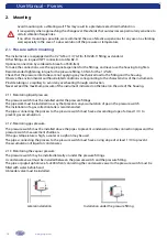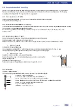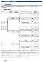
User Manual - P series
13
www.georgin.com
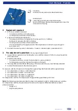
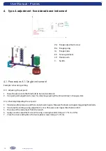
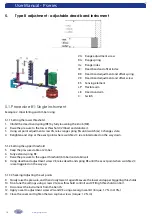
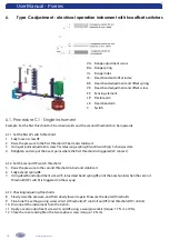
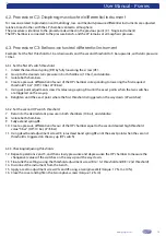
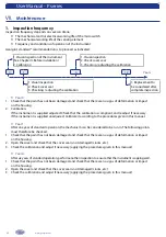
Clockwise:
Increases the set point and/or dead band value.
Anticlockwise:
Lowers the set point and/or dead band value.
Note: for RTPE type, the dead band adjustment screw VE is
internal to the housing.
2. Equipment required
»
A 1% class calibration standard:
-
For pressure switches: a pressure gauge
-
For temperature switches: a thermometer
»
A pressure or temperature generator:
-
For pressure switches: an air generator for pressures from -1 to 80 bar;
Hydraulic for pressures from 80 to 1000 bar
-
For temperature switches: a thermostatic bath
The coolant fluid must be appropriate for the temperatures concerned (e.g. water-glycol
from -20 to 0°C).
»
An electric low level system (1 oh 1 indicator light) - powered at 24 V ≈
3. Pre-adjustment operations
(for any type of adjustment)
»
Loosen the two captive screws holding the cover, and then remove it. Perform a visual inspection
of the instrument.
»
Install the instruments:
-
For pressure switches: connect the instrument to a pressure bench
-
For temperature switches: immerse the bulb(s) in the bath
»
The range (RG) and dead band (RE) springs, if the instrument has any, must be fully extended.
»
Connect the terminal(s) to the electrical system.
For pressure switches, the pressure change when approaching the thresholds will be approximately:
»
For a threshold < 2.5 mbar: ≤ 0.025 mbar/min
»
For a threshold < 10 mbar: ≤ 2.5 mbar/min
»
For a threshold < 100 mbar: ≤ 3.5 mbar/min
»
For a threshold > 100 mbar: ≤ 5% EM/min
For temperature switches, the temperature change will be approximately 0.5°C/min.
Note
: The following procedures describe the steps to be applied in order to calibrate pressure switches.
For temperature switches, the procedure is the same as for single or differential bellows-actuated
pressure switches:
-
Adjust in °C.
-
Vary the temperature.
VG
VE


