November 2016
Service and Repair Manual
Steer Axle Components
Part No. 1272220GT
GS-2669 DC • GS-3369 DC • GS-4069 DC
71
Steer Axl e Co mpon ents
8-1 Yoke As sem bly
8-1
Yoke Assembly
How to Remove the Yoke
1
Chock both sides of the wheels at the
non-steer end of the machine.
2
Center a lifting jack under the drive chassis at
the steer end of the machine.
3
Loosen the wheel lug bolts. Do not remove
them.
4
Raise the machine approximately 2 inches / 5
cm. Place blocks under the chassis for
support.
Crushing hazard. The chassis
will fall if not properly supported.
5
Remove the wheel lug bolts. Remove the tire
and wheel assembly.
6
Support and secure the yoke and assembly
with a lifting device.
Left side yoke:
7
Remove the retaining fasteners from the tie
rod pivot pin.
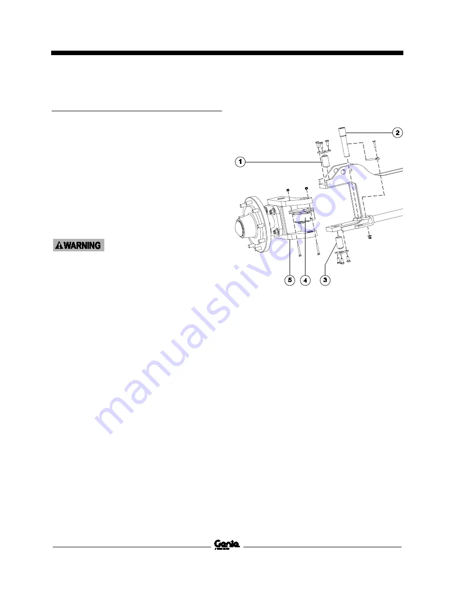
1 upper king pin
2 tie rod pivot pin
3 lower king pin
4 steer sensor assembly
5 yoke assembly
8
Use a small pry bar to move the pivot pin down
enough to clear the steer sensor assembly.
9
Remove the steer sensor actuator and spring
from the tie rod pivot pin and set aside.
10 Remove the steer sensor assembly and set it
aside.
11 Using a soft metal drift pin and a mallet, drive
the pivot pin up to remove it.
Содержание GS-2669 DC
Страница 59: ...Service and Repair Manual November 2016 Manifolds 48 GS 2669 DC GS 3369 DC GS 4069 DC Part No 1272220GT...
Страница 134: ...November 2016 Service and Repair Manual 123 Fuse Ground and Platform Control Boxes Fuse Box Layout All Models...
Страница 137: ...Service and Repair Manual November 2016 126 Ground Control Box Layout All Models...
Страница 138: ...November 2016 Service and Repair Manual 127 Platform Control Box Layout Models with 2 Speed Lift...
Страница 141: ...Service and Repair Manual November 2016 130 Platform Control Box Layout Models with Proportional Lift...
Страница 178: ......


