Model IR400
10
Fasten the IR400 wires to a wiring connector inside the junction box, IR4000M or IR4000S
enclosure. Once the two units are attached, you may replace the cover on the enclosure
attached to the IR400 using the four captive screws, or leave it off until additional cabling
from the enclosure is completed.
3.2 Mounting Instructions
The IR400 is mounted using the bolt holes on an attached junction box, IR4000M or IR4000S
enclosure. The IR4000M(S) is often mounted remote from the IR400 units, in order to locate it
within easy reach and at eye level.
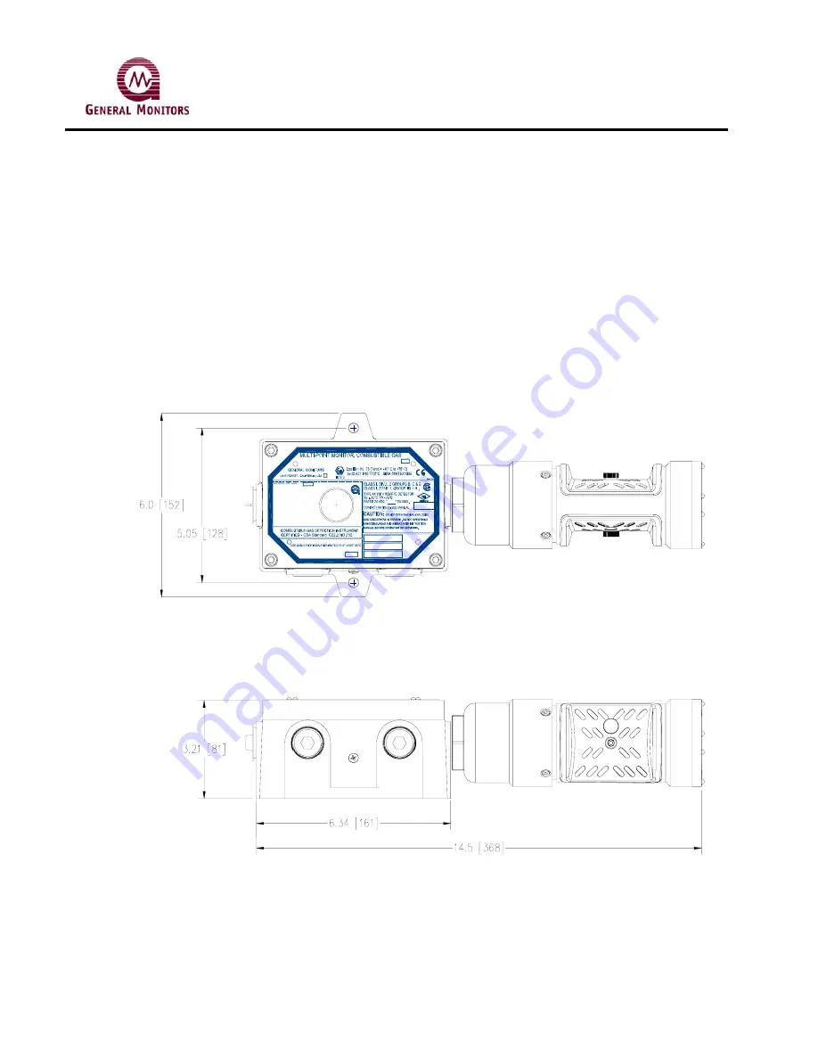
3.2.1 Mounting an IR400 with an Attached Enclosure
The following figure shows the overall and mounting dimensions for the Model IR400 with an
attached junction box / IR4000M(S) enclosure.
YEAR OF CONSTRUCTION
MODEL IR4000M
P/N 32580
CONFIG
MAN
S/N
0518
0539
CALIBRATION PROCEDURE
1. HAVE DETECTOR IN CLEAN AIR
2. APPLY MAGNET, AND WAIT FOR "AC"
ON DISPLAY
3. REMOVE MAGNET, WHEN d# IS
DISPLAYED, APPLY MAGNET TO
SELECT DETECTOR #
4. REMOVE MAGNET, FLASHING "AC"
IS DISPLAYED
5. WHEN "AC" IS STEADY, APPLY GAS
6. WHEN GAS IS DETECTED, "CP" IS
DISPLAYED
7. WHEN CALIBRATION IS COMPLETE,
"CC" IS DISPLAYED
8. REMOVE GAS
ALARM LED
WARN LED
Figure 5a. IR400 Mounting Dimensions
Содержание IR400
Страница 2: ......
Страница 15: ...Model IR400 11 Figure 5b IR400 Mounting Dimensions with a European Box ...
Страница 20: ...Model IR400 16 Figure 7 Wiring Diagram from IR400 to Control Equipment ...
Страница 41: ...Model IR400 37 9 6 Engineering Documentation ...
Страница 45: ...Model IR400 HART Field Device Specification for Point IR Gas Detector ...
Страница 78: ...Model IR400 Infrared Point Detector for Hydrocarbon Gas Applications Modbus programming guide ...


