ENGLISH
14
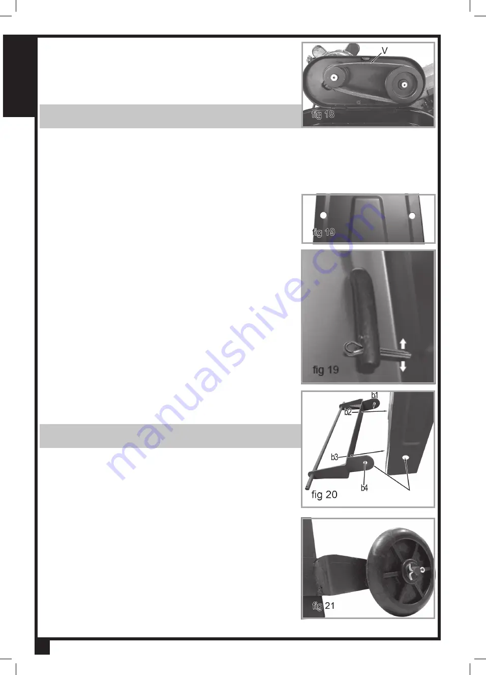
13. Locate the V-Belt.
14. Lift the hinged motor and place the V-belt around the top grooves of
both the motor pulley and the worm gear pulley.
15. Lower the hinged motor.
16. The band saw is now set at a speed of 80 f.p.m. (24 m/min).
17.
Fully tighten the motor adjusting knob (k, fig 11) by rotating it clockwise.
NOTE:
By tightening the adjusting knob, the v-belt is fully tightened on
the pulleys.
18.
Tension is correct when the belt deflects by about 1/2 an inch (13 mm)
at their center of run when using reasonable thumb pressure.
19. Close band saw upper pulley cover.
TRANSPORT HANDLE
1. Locate the transport handle.
2. Place the ends of the transport handle through the 2 holes of the leg
assembly at the opposite side of the motor (fig 18)
.
3. Locate two 3 x 18 cotter pins.
4.
Place a cotter pin through the hole at each end of the floor stand handle;
now located inside the floor stand.
5. Using pliers, wrap 1 leg of each cotter pin around the transport handle
(fig 19 shows one side of the handle inside the leg assembly)
.
6. Wrap the other leg of each cotter pin, in the opposite direction, around
the transport handle.
WHEELS
1.
Locate the wheel frame (E, fig 2)
.
2.
Place the wheel frame against the bottom of the floor stand.
NOTE:
Install the wheel frame on the same end of the band saw as the
motor.
3.
Align the holes of the wheel frame with the holes of the floor stand.
When aligning the holes, make sure the wheel frame is level with the
ground.
4. Locate 8 M8 washers, 4 M8 hexagon nuts and 4 M8 x 16 hexagon head
bolts.
5. Place a washer onto each hexagon head bolt.
6.
Insert one hexagon head bolt with washer, first through each hole of the
wheel frame, then into the floor stand, for a total of 4 bolts.
7. Place a washer onto the threaded ends of each inserted bolt.
8. Fully thread and tighten a hexagon nut onto the threaded ends of each
inserted bolt.
9. Locate 2 wheels and two 3 x 18 cotter pins.
10. Slide 1 wheel onto each side of the wheel frame axle.
11. Insert 1 cotter pin into each hole of the wheel frame axle.
12.
Using pliers, wrap the 1 leg of the cotter pin around the axle (fig 21)
.
13. Wrap the other leg of the cotter pin, in the opposite direction, around
the axle.
Содержание BS5205
Страница 50: ...FRANÇAIS 50 ...


