Integrated L-Band Up/Dn Converter
LT3600
CG-1309
Page 7
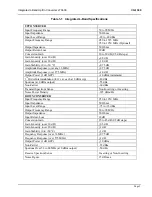
1.4 SPECIFICATIONS
The specifications for the Integrated L-Band
Up/Dn Converter are listed in Table 1-1, along
with the mechanical dimensions.
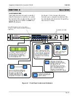
1.5 FRONT PANEL
All the operating controls and indicators for the
Integrated L-Band Up/Dn Converter are
located on the front panel. The front panel is
depicted in Figure 1-1. Alarm and level
monitoring of the L-Band Up/Dn Converter
CCA, an external LNB, and SSPB modules is
accomplished through the front panel display
and keboard interface.
1.6 REAR PANEL
The rear panel is depicted in Figure 1-2. It
incorporates, from left to right, Grounding Lug
(GND), Power Connector, Optional 10MHz
high stability reference output (J1), 10 MHz
reference input (J2), IF Out (J3), L-Band In
(J4), On/Off Switch for Dc output on J4
(SW2), Cooling Fans, Down Converter
StarSwitch Interface (Opt.) (J5), SSPB monitor
and control (J6), Remote Serial Interface (J7),
Up Converter StarSwitch Interface (Opt.) (J8),
IF In (J9), On/Off Switch for Dc output on J10
(SW3), L-Band Out (J10).
In the lower right hand side of the rear panel is
a label that refers to the operation and
maintenance manual and revision level that
applies to this converter.
1.7 COOLING
Cooling of the equipment is achieved by
pulling in cool air through the two side inlet
grills. The heated air exits the equipment
through the two rear panel mounted exhaust
fans.
Figure 1-1 Front Panel w/Keypad and LCD Display
Figure 1-2 Rear Panel


