


Installation Manual for PV Link and SnapRS
17
Section 6 Operating Instructions
User Interface via Inverter
PV Link Information and control features are
available on the PWRcell Inverter control
panel when REbus is energized. See the Gen
-
erac PWRcell Inverter Owner’s Manual for
more information.
See
.
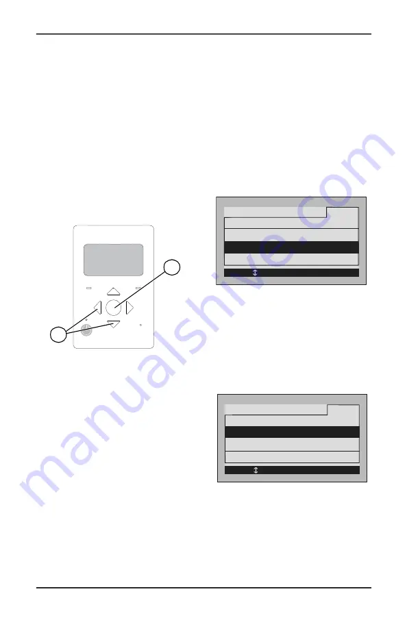
To access the device page for
each PV Link, use left or right arrow buttons
(A) on the inverter control panel to scroll
through the pages. When on a PV Link device
page, press center button (B) to enable or dis
-
able the device or to modify settings. The dis
-
abled/enabled state does not affect
communication with the inverter.
NOTE:
The PV Link only produces power after
the REbus DC nanogrid has been established
and the device has been enabled.
Figure 6-1. Inverter Control Panel
Commissioning PV Link
The PV Link ships from the factory in a dis
-
abled state. Each unit must be enabled from
the PWRcell Inverter control panel. Once the
inverter is enabled and REbus voltage is pres
-
ent at the PV Link, the PV Link will be able to
communicate on the system. After properly
enabling the PV Link, it will detect the REbus
nanogrid and begin exporting power based on
the system mode and settings selected.
See the PWRcell Inverter Installation and
Owner's Manual for more information on sys
-
tem modes and commissioning.
To enable and commission PV Link:
– Ensure REbus +/- are connected with
correct polarity to each PV Link.
– Ensure each PV Link has a low resis
-
tance ground connection to the inverter
ground bar.
– Ensure PWRcell Inverter DC Discon
-
nect(s) are in the ON position for each
PV Link.
– Ensure inverter is enabled.
Commissioning with SnapRS
Devices for PVRSS
To enable PV Link to work as a PVRSS with
SnapRS devices:
1.
Press the right arrow button on the control
panel until the PV Link device page
appears.
NOTE:
The device page should read Dis
-
abled. If it does not read Disabled, press the
center button and disable the device.
2.
Record the RCPn in
, found on
the front cover of this manual.
Figure 6-2. Enable w/PVRSS
3.
See
. Press the center button
and select Enable w/PVRSS to enter the
Testing PVRSS state.
4.
See
.
Press the center button
and select Mod. Settings to access Device
Settings and Options.
5.
See
. If installing parallel series
substrings for high voltage modules, select
Mod. Setting and update the string count
value to 2.
Figure 6-3. PVRSS Commissioning (1 of 3)
009894
REbus
Inverter
Internet
Shutdown
(hold)
B
A
Disable
PV Link S2502
Menu
Mod. Setting
s
RCPn: 00010003XXXX
< EXIT SCROLL > NEXT • SELECT
Enable w/PVRSS
010032
Disable
PV Link S2502
Menu
Mod. Settings
Enable w/PVRSS
RCPn: 00010003XXXX
< EXIT SCROLL > NEXT • SELECT
010030
Содержание PV Link 010023
Страница 4: ...This page intentionally left blank...
Страница 8: ...4 Installation Manual for PV Link and SnapRS This page intentionally left blank...
Страница 12: ...8 Installation Manual for PV Link and SnapRS This page intentionally left blank...
Страница 14: ...10 Installation Manual for PV Link and SnapRS This page intentionally left blank...
Страница 16: ...12 Installation Manual for PV Link and SnapRS This page intentionally left blank...
Страница 24: ...20 Installation Manual for PV Link and SnapRS This page intentionally left blank...
Страница 26: ...22 Installation Manual for PV Link and SnapRS This page intentionally left blank...
Страница 29: ...Installation Manual for PV Link and SnapRS 25 This page intentionally left blank...
Страница 30: ...26 Installation Manual for PV Link and SnapRS This page intentionally left blank...
Страница 31: ......


