

iSXblue/SXBlue II GNSS Series Technical Reference Manual
47
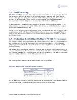
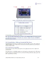
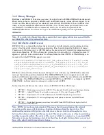
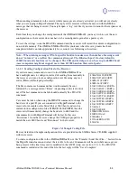
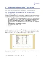
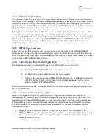
Figure 2-3 RS-232 Connector Pin-out
Table 2-4 Serial Port Pin-out, RS-232C Interface Level
* PPS, EM and PWR are available upon request at time of purchase
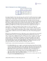
Note - For successful communications, the baud rate of the iSXBlue/SXBlue II serial ports must be
set to match that of the devices to which they are connected. Chapter 5 describes the $JBAUD
baud rate change command.
2.8.3
Event Marker, 1 Pulse per Second and 5Vdc Power
The 1PPS, EM and 5Vdc Power are available upon request on the DB-9 connector when ordering the
iSXBlue/SXBlue II receiver. These features can also be activated after purchase but you will need to
contact your local reseller.
2.8.3.1
One Pulse per Second (1PPS)
The one pulse per second (1 PPS) timing signal is used in applications where devices require time
synchronization.
The 1 PPS signal is 3.3V HCMOS normally low with rising edge synchronization. The 1 PPS signal is
capable of driving a load impedance which is greater than 10 k
Ω
in parallel with 10 pF capacitor. The
pulse is approximately 1ms long.
iSXBlue/SXBlue II GNSS
Pin
Signal
Description
2
TXD
NMEA 0183, binary, and RTCM (output)
3
RXD
NMEA 0183, binary, and RTCM (input)
5
GND
Signal Ground
6*
1PPS*
One Pulse Per Second (Output)
8*
EM*
Event Marker (Input)
9*
PWR*
Power 5VDC @ 100mA (max) (Output)
#2 - TX
#3 - RX
#5 - GND
#1
#5
#6
#9


