Navman Halo Qube 2, Installation Manual
The Navman Halo Qube 2 is a cutting-edge device designed to enhance your navigation experience. Ensure seamless installation with our convenient and comprehensive Installation Manual, available for free download at manualshive.com. This manual provides step-by-step instructions and valuable insights to make your journey stress-free and enjoyable.
Share
Download


Reviews:
No comments
Related manuals for Halo Qube 2

nuvi 880
Brand: Garmin Pages: 118

VP4150
Brand: Interlink electronics Pages: 2

N10
Brand: LG Pages: 54

N11
Brand: LG Pages: 48

GPS Kit
Brand: Garmin Pages: 54

MG2639
Brand: Zte Pages: 47
GPSMAP 296 - Aviation GPS Receiver
Brand: Garmin Pages: 2
Tracker-007
Brand: Holux Pages: 25

GM-82
Brand: Holux Pages: 4

GPSlim 236B
Brand: Holux Pages: 22

961
Brand: NorthStar Pages: 404
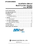
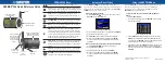
MFDBB
Brand: Furuno Pages: 48

GH1202
Brand: Teltonica Pages: 37

FreeBird 50.6HD
Brand: Lark Pages: 46

STI_GL300
Brand: Spytec Pages: 6
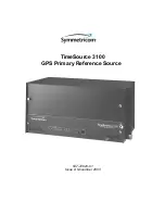
TimeSource 3100
Brand: Symmetricom Pages: 238

TK102-2
Brand: Satellite Communication Pages: 10

Eclipse AVN2210p
Brand: TomTom Pages: 43


