Smart IP Manager - System Operating Manual
page 14 of 48
4.4 Connecting Ethernet and PoE to loudspeakers
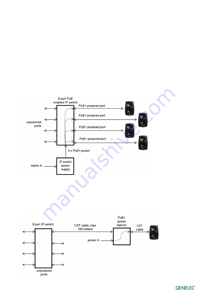
Example of powering the Smart IP loudspeaker with a PoE+ enabled IP switch. With this method,
the power budget available for all outputs connected to the IP switch must enable each Smart IP
loudspeaker to run at full PoE+ power. For 4 loudspeakers, the power supply must support 4 x
PoE+ power level.
Connect an Ethernet cable from the PoE+ output in an IP switch to the Smart IP loudspeaker
Ethernet port. Use at least CAT5 cable or better. Press the power switch to power up the
loudspeaker.
Figure 7. Smart IP loudspeakers powered with PoE+ IP switch.
Example of powering the Smart IP loudspeaker with a PoE+ power injector. This method enables
the use of standard non-PoE IP switches. Each power injector must support full PoE+ power level
into the device.


