background image


Rev. 01  08/20


14  

  Product description 

OptiFlex Pro BN 


Reasonably foreseeable misuse 

– 

Operation without the proper training 

– 

The use of electrically conducting powders (like metallic or graphite 
powders) 

– 

Use with insufficient compressed air quality and grounding 

– 

Use in connection with unauthorized coating devices or components 


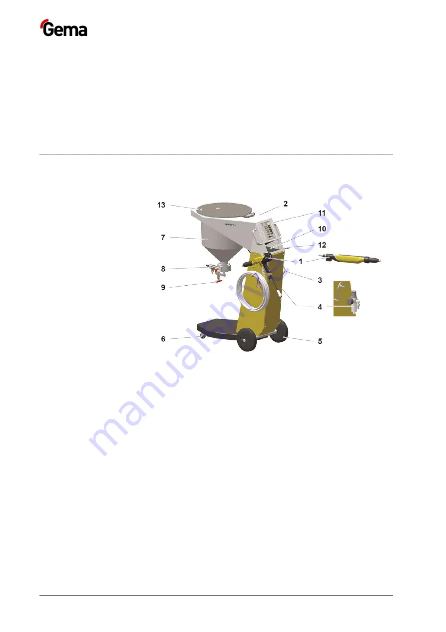
Structure 

Overall view 


fig. 2 

OptiSelect Pro GM04 manual 
powder gun or OptiGun GA03 
automatic powder gun 

Frame 

Hose holder 

Filter unit 

Rubber wheel 

Swivel wheel 

Stirrer hopper 

OptiFlow injector 

Discharge flap 

10  Shelf 
11  OptiStar CG21 Gun 

control unit 

12  Gun holder 
13  Filler flap 


OptiStar 4.0 Gun control unit 

All information about the OptiStar 4.0 (Type CG21) manual gun control 
unit can found in the documentation for that equipment (enclosed with this 
manual)! 

OptiFlow injector 

All information about the OptiFlow injector will be found in the 
corresponding enclosed documentation! 

Содержание OptiFlex Pro BN

Страница 1: ...ipment OptiFlex Pro BN This equipment was developed for use with electrically non conducting powders The use of electrically conducting powders like metallic or graphite powders can cause a permanent decrease of functioning Translation of the original operating instructions ...

Страница 2: ...f Gema Switzerland GmbH All other product names are trademarks or registered trademarks of their respective holders Reference is made in this manual to different trademarks or registered trademarks Such references do not mean that the manufacturers concerned approve of or are bound in any form by this manual We have endeavored to retain the preferred spelling of the trademarks and registered trade...

Страница 3: ...racteristics properties of the functions 16 Processing the powder from the stirrer recipient 16 Technical Data 17 Connectable guns 17 Electrical data 17 Pneumatic data 17 Dimensions 18 Processible powders 18 Environmental conditions 18 Sound pressure level 18 Rating plate 19 Assembly Connection 21 Set up 21 Assembly guide 21 Connection instructions 22 Adaptor for external triggered powder guns Bor...

Страница 4: ...le 38 Maintenance works 38 Maintenance Repairs 39 General information 39 Interval 39 Daily maintenance 39 Weekly maintenance 39 Biannually maintenance 40 If in disuse for several days 40 Gun maintenance 40 Maintenance of the filter unit 40 Cleaning 42 Gun cleaning 42 Cleaning the powder container 42 Repair work 43 Periodic checks 43 Fault clearance 45 Disposal 47 Introduction 47 Requirements on pe...

Страница 5: ...ual describes all options and functions of this manual coating equipment Please note that your manual coating equipment may not be equipped with all described functions Options are marked by double asterisks Keeping the Manual Please keep this Manual ready for later use or if there should be any queries Safety symbols pictograms The following warnings with their meanings can be found in the Gema i...

Страница 6: ...r the environment MANDATORY NOTE Information which must be observed NOTICE Useful information tips etc Structure of Safety Notes Every note consists of 4 elements Signal word Nature and source of the danger Possible consequences of the danger Prevention of the danger SIGNAL WORD Nature and source of the hazard Possible consequences of the danger Prevention of the danger Presentation of the content...

Страница 7: ...ety regulations Work should only be carried out in accordance with the instructions of the relevant documents Always work with the complete original document Basic safety instructions This product is built to the latest specification and conforms to the recognized technical safety regulations and is designed for the normal application of powder coating Any other use is considered non compliant The...

Страница 8: ...s as well as other generally recognized safety regulations occupational health and structural regulations are to be observed Furthermore the country specific safety regulations also must be observed Additional safety and operation notices can be found on the homepage www gemapowdercoating com General dangers Start up is forbidden until it has been established that the product has been set up and w...

Страница 9: ...ons leading to dangerous levels of dust concentration in the powder spraying booths or in the powder spraying areas must be avoided There must be sufficient technical ventilation available to prevent a dust concentration of more than 50 of the lower explosion limit UEG max permissible powder air concentration If the UEG is not known then a value of 10 g m should be considered see EN 50177 All unau...

Страница 10: ...coating booth the recovery unit and the conveyor chain respectively with the suspension arrangement of the objects Smoking and open flames Fire and smoke prohibition Smoking and igniting fire are forbidden in the entire vicinity of the system No work that could potentially produce sparks is allowed Stay for persons with cardiac pacemakers The stay for persons with cardiac pacemakers is forbidden A...

Страница 11: ...ctive clothing e g facemasks A dust mask corresponding to filter class FFP2 or N95 at minimum must be worn during any cleaning work The operating personnel must wear electrically conductive steel toe footwear e g ESD shoes The operating personnel should hold the gun with bare hands If gloves are worn these must also conduct electricity ...

Страница 12: ...Rev 01 08 20 12 Safety OptiFlex Pro BN ...

Страница 13: ...tiGun GA03 Automatic powder gun is ideally suited for spraying short bursts of fine grained powder with small powder output volumes Fig 1 Observance of the operating service and maintenance instructions specified by the manufacturer is also part of conformity of use This product should only be used maintained and started up by trained personnel who are informed about and are familiar with the poss...

Страница 14: ...elect Pro GM04 manual powder gun or OptiGun GA03 automatic powder gun 2 Frame 3 Hose holder 4 Filter unit 5 Rubber wheel 6 Swivel wheel 7 Stirrer hopper 8 OptiFlow injector 9 Discharge flap 10 Shelf 11 OptiStar CG21 Gun control unit 12 Gun holder 13 Filler flap OptiStar 4 0 Gun control unit All information about the OptiStar 4 0 Type CG21 manual gun control unit can found in the documentation for ...

Страница 15: ... 9 Powder hose Ø 12 5 9 5 mm for lengths 6 12 m 8 Hose connection 9 5 mm 300 and 500 mm extensions special lengths on request Scope of delivery OptiSelect Pro GM04 manual powder gun or OptiGun GA03 automatic gun with gun cable powder hose electrode rinsing air hose and standard nozzle set For more on this see the gun operating manual OptiStar 4 0 Control unit in a metal case with power supply cabl...

Страница 16: ...of the functions Processing the powder from the stirrer recipient The type S manual coating equipment allows for powder to be processed directly out of the stirrer recipient Because of the conical shape of the stirrer recipient the powder can be used completely optimum powder consumption ...

Страница 17: ... 120 230 240 VAC Frequency 50 60 Hz Fluctuations of the power supply 10 Overvoltage category OVC II Connected load 150 VA Nominal output voltage to the gun 12 V Nominal output current to the gun 1 2 A Connection and output for vibrator on Aux output 100 240 VAC max 100 W Connection for rinsing function valve 24 VDC max 3 W Protection type IP54 Approvals II 3 D preset country specific voltage Pneum...

Страница 18: ...emperatures to 31 C linearly decreasing to 50 relative humidity at 40 C Environment not for wet environment Degree of pollution of the intended environment 2 in accordance with DIN EN 61010 1 Sound pressure level OptiFlex Pro BN Normal operation 60 dB A The sound pressure level was measured while the unit was in operation measurements were taken at the most frequent operator positions and at a hei...

Страница 19: ...Rev 01 08 20 OptiFlex Pro BN Product description 19 Rating plate fig 4 ...

Страница 20: ...Rev 01 08 20 20 Product description OptiFlex Pro BN ...

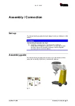
Страница 21: ...unding temperature too high Install the equipment only in locations with an ambient temperature of between 5 and 40 C i e never next to heat sources such as an enameling furnace or electromagnetic sources such as a control cabinet Assembly guide The manual coating equipment must be set up in accordance with the setup and connecting instructions included with delivery fig 5 ...

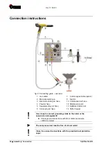
Страница 22: ...6 Conveying air hose 7 Control signal cable option 8 Injector 10 Compressed air hose 12 Maintenance unit 13 OptiStar Control unit 14 Stirrer hopper Use clamp to connect grounding cable to the cabin or the suspension arrangement Check ground connections with Ohm meter and ensure 1 MOhm or less The compressed air must be free of oil and water Close the unused connections with the provided dust prote...

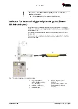
Страница 23: ... Gun control unit and externally triggered by short circuiting the two cables of the adaptor piece The adaptor must be switched between the powder gun and the Gun Control unit The two wire cable can be connected to a relay output of a PLC which short circuits both fig 7 Remote triggering Connecting guide 1 Trigger Adapter for remote triggering order no 1002 772 2 OptiStar Control unit 3 Automatic ...

Страница 24: ...Rev 01 08 20 24 Assembly Connection OptiFlex Pro BN ...

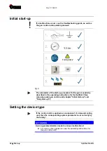
Страница 25: ... When starting up the gun control unit the following general conditions impacting the coating results must be taken into consideration Gun correctly connected Gun control unit correctly connected Corresponding power and compressed air supply available Powder preparation and powder quality OK ...

Страница 26: ...in the operating instructions for the OptiStar CGxx manual powder gun control unit chapter Initial start up and Daily start up Setting the device type If the control unit is supplied as a component of a manual coating unit then the corresponding system parameter is set correctly by the factory ATTENTION A wrong parameterization leads to various malfunctions For more on this please also see the ope...

Страница 27: ... powder can cause respiratory issues or cause a slippage falling hazard The manual equipment may only be operated in conjunction with a sufficiently powerful suction unit such as Gema Classic Open booth 1 Fill the stirrer hopper with powder a Open the hinged flap of the stirrer hopper cover CAUTION Hand injury If the cover to the agitator unit is opened then this can fall shut again during inatten...

Страница 28: ... application modes have preset values for high voltage and spray current Application mode Preset kV Preset µA flat parts 100 100 complicated parts 100 22 overcoat 100 10 3 The air values for total air powder output and electrode rinsing air can be individually defined and are saved in the programs Starting the individual adjustable programs 1 Turn on the gun control unit with the ON key 2 Press th...

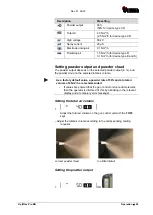
Страница 29: ...r output in and the powder cloud on the selected total air volume As a factory default value a powder rate of 50 and a total air volume of 4 Nm h are recommended If values are entered that the gun control unit cannot implement then the operator is informed of this by a blinking in the relevant display and a temporary error message Setting the total air volume 1 Adjust the total air volume on the g...

Страница 30: ...an overly high powder volume where possible 2 Check fluidization of the powder in the powder container 3 Point the gun into the booth switch the gun on and visually check the powder output Setting the electrode rinsing air 1 Press the key The second display level will be shown 2 Adjust the correct electrode rinsing air according to the applied nozzles deflector plate flat jet nozzle 0 1 Nm h 0 5 N...

Страница 31: ...ent without optional PowerClean module system parameter P01 0 The rinsing mode can only be activated from standby mode main menu display no powder conveying On manual coating equipment type F the injector must be disconnected prior to cleaning procedure on type B the suction unit must be lifted and on type S the powder container must be empty 1 Detach the injector 2 OR 3 START ...

Страница 32: ...e is exited if the automatic rinsing sequence has finished Manual manual The operator controls the number and length of the PowerClean impulse by pressing the gun trigger a second time 4 STOP OR OR the cleaning mode is terminated automatically After completion of the PowerClean procedure the controller switches back to coating mode Manual equipment with optional PowerClean module system parameter ...

Страница 33: ...leaning of other components such as the fluid intake unit powder container etc The rinsing mode is exited if the automatic rinsing sequence has finished Manual manual The operator controls the number and length of the PowerClean impulse by pressing the gun trigger a second time 3 STOP OR OR the cleaning mode is terminated automatically After completion of the PowerClean procedure the controller sw...

Страница 34: ...Rev 01 08 20 34 Operation OptiFlex Pro BN Setting the background illumination 1 Press the key The display switches to the following level 2 Select the desired brightness ...

Страница 35: ... rear of the powder gun remote control or on the control unit 4 Point the gun into the booth 5 Press the gun trigger The rinsing process is started 6 Clean the stirrer hopper 7 Clean the powder hose Disconnect the powder hose from the hose connection on the injector Point the gun into the booth Blow through the hose manually with a compressed air gun Connect the powder hose again to the hose conne...

Страница 36: ...Rev 01 08 20 36 Operation OptiFlex Pro BN ...

Страница 37: ...er conveying see therefore the corresponding user manuals 3 Turn off the compressed air main supply Storage conditions Hazard notes There is no danger to personnel or the environment if the unit is stored properly Type of storage For safety reasons the product should only be stored in a vertical position Storage duration If the physical conditions are maintained the unit can be stored indefinitely...

Страница 38: ...ents Storage must be inside a dry building at a temperature between 5 and 50 C Do not expose to direct sunlight Maintenance during storage Maintenance schedule No maintenance schedule is necessary Maintenance works During long term storage periodically perform a visual check ...

Страница 39: ...ng quality The parts to be replaced during maintenance work are available as spare parts These parts can be found in the appropriate spare parts list Interval Daily maintenance 1 Clean the injector see therefore the user manual of the OptiFlow injector 2 Clean the powder gun For more on this please also review the user manual for the OptiSelect GM03 manual powder gun 3 Clean the powder hose Please...

Страница 40: ...2 Point the gun into the booth 3 Blow through the hose manually with a compressed air gun 4 Connect the powder hose again to the hose connection on the injector Gun maintenance The gun is designed to require only a minimum amount of maintenance 1 Clean the gun with dry cloth see chapter Maintenance 2 Check connection points to powder house 3 Replace the powder hoses if necessary Maintenance of the...

Страница 41: ...Rev 01 08 20 OptiFlex Pro BN Maintenance Repairs 41 fig 10 3 Replace the filter element 4 Clean the filter glass on the inside and install it again ...

Страница 42: ...toluene trichloroethylene xylene Only cleaning agents with a flash point of a least 5 Kelvin above the ambient temperature or cleaning places with technical ventilation are allowed Before cleaning the powder gun switch off the control unit The compressed air used for cleaning must be free of oil and water Daily 1 Blow off the outside of the gun and wipe clean etc Weekly 2 Remove powder hose 3 Remo...

Страница 43: ...at the bottom of the powder hopper 6 Remove the cover take care not to damage the stirrer arm 7 Blow off with compressed air the hopper cover and stirrer arm and wipe with a clean dry brush and a clean cloth 8 Carefully close the cover again taking care of the stirrer arm and fit the injector and hoses The coating equipment is now ready for operation Do not refill the powder hopper until just befo...

Страница 44: ...Rev 01 08 20 44 Maintenance Repairs OptiFlex Pro BN ...

Страница 45: ...e fuse Power pack defective Contact local Gema representative Gun LED remains dark although the gun is triggered High voltage adjustment is set too low Increase high voltage Gun plug or gun cable defective Contact local Gema representative LED on gun defective Contact local Gema representative Powder does not adhere to object although the gun is triggered and sprays powder High voltage and current...

Страница 46: ...r volume on the control unit Bend or damage to air lines to injector Check air lines to injector Insert sleeve in the injector worn or not inserted Replace or insert it Fluidization not running see below No electrode rinsing air Rinsing air throttle motor defective Contact local Gema representative The powder is not fluidized Compressed air not present Connect the equipment to the compressed air F...

Страница 47: ... Gema the instructions in the respective manufacturer s documentation must be observed Disposal regulations The product must be disassembled and disposed of properly at the end of its service life When disposing of the product the applicable local and regional laws directives and environmental regulations must be complied with Materials The materials must be sorted according to material groups and...

Страница 48: ...Rev 01 08 20 48 Disposal OptiFlex Pro BN ...

Страница 49: ... 15 mm When ordering cable or hose material the required length must also be given The spare part numbers of this bulk stock is always marked with an Wearing parts are always marked with a All dimensions of plastic hoses are specified with the external and internal diameter Example Ø 8 6 mm 8 mm outside diameter o d 6 mm inside diameter i d ATTENTION Use of non original Gema spare parts When using...

Страница 50: ...5 1 Quick release connection NW5 Ø 8 mm red 261 645 5 2 Nut with kink protection M12x1 mm Ø 8 mm 201 316 5 3 Plastic tube Ø 8 6 mm red 103 500 7 Stirrer hopper see corresponding spare parts list 8 Swivel wheel Ø 50 mm 260 606 12 Rubber wheel Ø 200 mm 260 592 13 Hose clamp Ø 15 18 mm 203 386 14 Quick release connection NW7 8 Ø 10 mm 239 267 15 Pneumatic group complete see corresponding spare parts ...

Страница 51: ...Rev 01 08 20 OptiFlex Pro BN Spare parts list 51 OptiFlex Pro BN Spare parts fig 11 ...

Страница 52: ...r discharge flap 303 240 12 Discharge flap with toggle clamp incl pos 11 303 194 13 Blind grommet complete incl pos 14 380 296 14 O ring for blind grommet 231 517 15 Injector holder 380 288 16 Feather key 4x4x12 mm round 269 263 17 Feather key for cardan joint 4x4x16 mm round 206 075 18 Allen grub screw for cardan joint sharp M4x5 mm 214 728 19 Allen cylinder screw M3x10 mm 248 444 20 Cylinder rib...

Страница 53: ...Rev 01 08 20 OptiFlex Pro BN Spare parts list 53 Stirrer hopper Spare parts fig 12 Stirrer hopper Spare parts ...

Страница 54: ...ck Stirrer Control Power Supply 389 277 5 Mains push button complete with cable 390 542 Cable set consisting of 6 Power pack connecting cable 390 550 7 Connecting cable 24 VDC 390 569 8 Grounding wire 391 867 9 Fixture set for power pack board consisting of two pieces each Spacer M3 SW5 5x12 mm 267 775 Spacer M3 SW5 5x10 mm 267 007 Cylinder screw 245 321 Shake proof washer 205 885 10 Fuse 2 AT 221...

Страница 55: ...Rev 01 08 20 OptiFlex Pro BN Spare parts list 55 Stirrer drive unit Spare parts fig 13 Stirrer drive unit Spare parts ...

Страница 56: ... valve 1008 238 3 Connector NW7 4 1 4 256 730 4 Elbow joint 1 4 1 4 222 674 5 Sealing plug 1 8 203 297 6 R F unit 0 8 bar 1 4 complete incl pos 1 and 2 1008 236 7 Double nipple 1 4 1 4 divisible 261 165 8 Pressure gauge 0 10 bar 1 8 1008 049 9 Distribution block 1017 816 10 Screw in nipple 1 4 Ø 8 mm 265 136 11 Plug Ø 8 mm 238 023 Wearing part fig 14 Pneumatic group ...

Страница 57: ...Rev 01 08 20 OptiFlex Pro BN Spare parts list 57 ...

Страница 58: ......

Страница 59: ...ral days 37 E Electrical data 17 Environmental conditions 18 F Fault clearance 45 Figure references in the text 6 I Intended use 13 M Maintenance 39 Maintenance during storage 38 O Operation 27 P Periodic checks 43 Pictograms 5 Pneumatic data 17 Presentation of the contents 6 Product description 13 R Rating plate 19 Repair work 43 Repairs 39 S Safety 7 Safety symbols 5 Shutdown 37 Sound pressure l...

Страница 60: ...Rev 01 ...

Отзывы: