


Notes on use of the GT with the digital On/Off control
CALIBRATION PROCEDURE OF THE INTERRUPTED LOAD ALARM
The interrupted load alarm function enables the GT to diagnose a variation of the load current (compared to a set limit),
distinguishing it from one caused by a change in grid voltage. The solid state power unit must therefore be supplied with the
voltage applied to the load terminals, i.e.: LOAD (L2): already connected internally;
LINE (h or i): connect terminal h for voltages from 150 to 300V; connect terminal i for voltages from 300 to 530V.
The alarm activates (relay closed and yellow alarm LED on) when the current, during the conduction of the device, falls below
a preset level that may be adjusted using the trimmer on the faceplate.
Calibration procedure (refer to the faceplate description drawing)
1) Use the adjustment system (or a calibrator) in order to supply the maximum signal (100% conduction or thered “ON” LED
always illuminated). As an alternative, you can configure the GT to 0-10 V DC input configuration and connect terminals 5
and 6.
2) Use a current sensing pliers to check that the load current is at rated level.
3) Turn alarm limit adjustment trimmer (g) fully clockwise. Check that yellow alarm LED (b) turns on.
4) Slowly turn trimmer (g) counterclockwise until the alarm LED turns off.
5) Turn the trimmer counterclockwise another 1/10 of a turn (1 notch on the scale).
In this way, the alarm limit is set below 10% of the rated load current.
N.B:
the partial load break alarm function operates with power partialization exceeding 15%. For partializations below 20%, tripping
times increase due to the reduced load activation time. For correct operation of the option, the load current has to exceed 30%
of rated current for the GT.
- The logic control signal has to be connected with the correct polarities to terminals 4 and 5 of the analog input.
- Turn minimum adjustment trimmer (d) fully counterclockwise and maximum adjustment trimmer (e) fully clockwise.
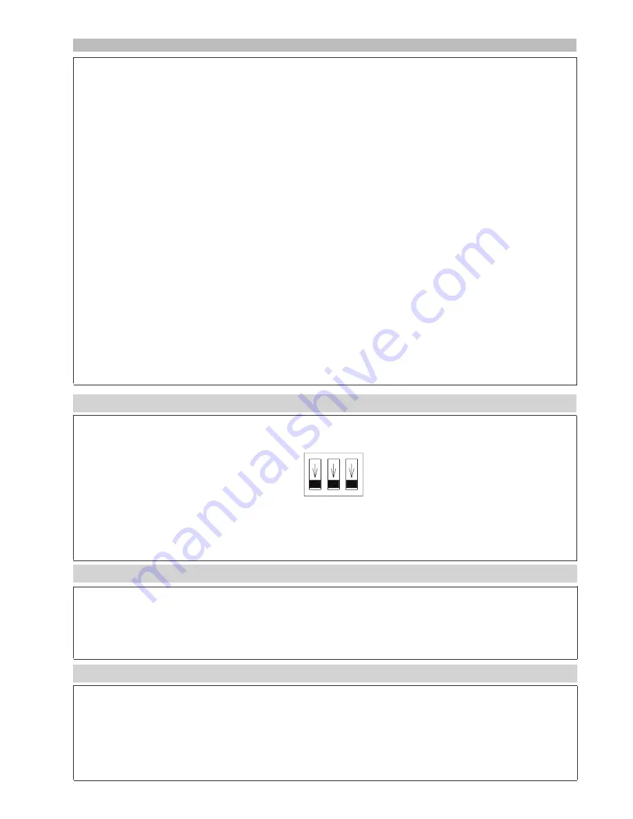
- Set the 3 dip switches (f) to off.
For applications with a very short work cycle, you can drive the solid state group by means of the Master/Slave signal by
driving it with a digital signal (OFF = 0 V dc; ON = from 4 V dc to 10 V dc)
Inhibiting the GT
You can inhibit operation of the GT by means of the Master/Slave signal.
To inhibit, connect control signal - (4) with the synchronism signal for Master/Slave connection (3).
Notes on use of the GT in Master/Slave configuration
The GT can be used as a master to drive other solid state groups (slaves). With Master/Slave signal (3), you can drive up to 9
GTs (see connection examples for GT solid state power relays with three-phase load). You can also use a GT to drive GS solid
state power relays (maximum of 2), as shown in the connection diagrams for GT/GS solid state power relays with three-phase
load (attention: the HB option cannot be used for a three-phase application with neutral).