


Operating instructions
GEFA / DOMINO valve AT 200F (ATEX II 1D/2DG c)
AT200F-ATEX-Betriebsanleitung (GB).doc (ZA) 21.09.2007
4 / 8
Installation
•
Observe the maintenance and repair instructions for the individual components.
•
Danger:
moving parts may cause injury.
•
Danger:
Operation of electrically, pneumatically, or hydraulically-operated valves that have not yet been
installed is not permitted.
•
To prevent the danger of stumbling: Place all connections (cable, hose pipes and tubing) in such a way that they
will not cause any stumbling (cable ducts, bridges etc).
•
Before the final installation of the valves, any corrosion preventative that has been applied as per section 2.2
above must be thoroughly removed. All parts, and in particular the valve plate, spindle and piston rod, must be
free of dust and dirt and, if necessary, well lubricated with a suitable lubricant before being used for the first
time.
•
Damage to the protected surfaces arising during installation or transport must be repaired by an expert.
Damage of this type is not covered by the warranty.
•
Protection of the Valve
If there is construction work still going on near or above the valves, they must be covered to protect them
against this construction work.
When painting the installation, the spindle, electrical components and the plate projecting from the housing
when the valve is open must not be painted. Any solvents used to remove unwanted paint must not come into
contact with the seals under any circumstances. This applies especially to the area where the valve plate
projects from the housing. If the installation is to be first cleaned by sand-blasting, the valves must be covered
with special care.
Debris from sand-blasting, and especially sand-blasting grit, which gets into those parts of the installation that
will be in contact with the valve during subsequent operation of the installation, must be removed carefully.
Sand-blasting grit can destroy the valve plates and seals within a very short time.
•
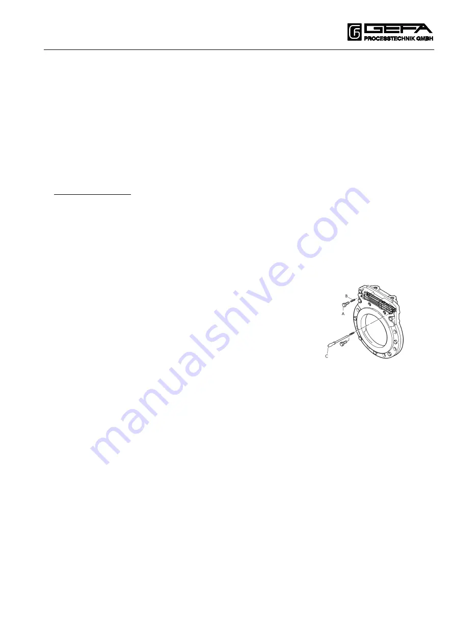
The possible locations for installing the valve must be selected such that
surfaces A and B are freely accessible for both sides to allow the seals to be
readjusted if necessary.
Ensure that there is the necessary amount of space (200mm) available for
the packing tool C.
•
Valves should normally be installed upright in horizontal pipelines, i.e.,
actuator on top, and horizontally in vertical pipelines.
The position of installation of the respective valve must be chosen so that
operation will be affected as little as possible by the medium.
In the case of technically difficult installation conditions or in the case of custom-made valves, please contact
the manufacturer if there is any doubt regarding the exact position of installation.
•
The direction of flow must be according to the direction of the arrow in custom-made valves.
•
The pipes must not have any tension.
•
Prior to the mounting of the valve flush the pipelines to remove all traces of soiling, welding residues etc.
•
Check whether the flange clearance is in accordance with the face-to-face dimension of the valve.
•
Before mounting the valve, the flanges are to be sufficiently spread using a suitable tool.
•
Danger:
From size 600 mm flange gaskets with supporting ring (e.g. spiral-wound gasket with outside ring)
must be used, because the permitted explosion pressure is higher than the nominal pressure of the valve /
flange connection
These gaskets are recommended for valves up to size 500 mm.
•
Insert the valve and the gaskets between the flanges.
•
Insert flange screws and nuts.
•
Remove the spreader and hand-tighten the screws.
•
Check whether the valve, the gaskets and the counter-flanges are in true alignment.
•
Before the flange screws at the area of the thread blind holes of the valve are tightened, the through screws
lying besides have to be tightend.
•
Tighten the flange screws crosswise using the stipulated torque.
The tightening moment depends on the seat material chosen.
If there are no details available, the following reference values can be used:
M16 = 125 Nm
M20 = 240 Nm
M24 = 415 Nm
M27 = 610 Nm
M30 = 830 Nm
M33 = 1100 Nm