CH1
CH2
CH3
CH4
CH5
CH6
+18
+12
+9
+6
+3
0
-20
+18
+18
+18
+18
+18
+18
+12
+12
+12
+12
+12
+12
+9
+9
+9
+9
+9
+9
+6
+6
+6
+6
+6
+6
+3
+3
+3
+3
+3
+3
0
0
0
0
0
0
-20
-20
-20
-20
-20
-20
+12
+12
+12
+12
+12
+12
+9
+9
+9
+9
+9
+9
260
1
2
3
4
5
6
7
8
9
10
11
12
13
14
15
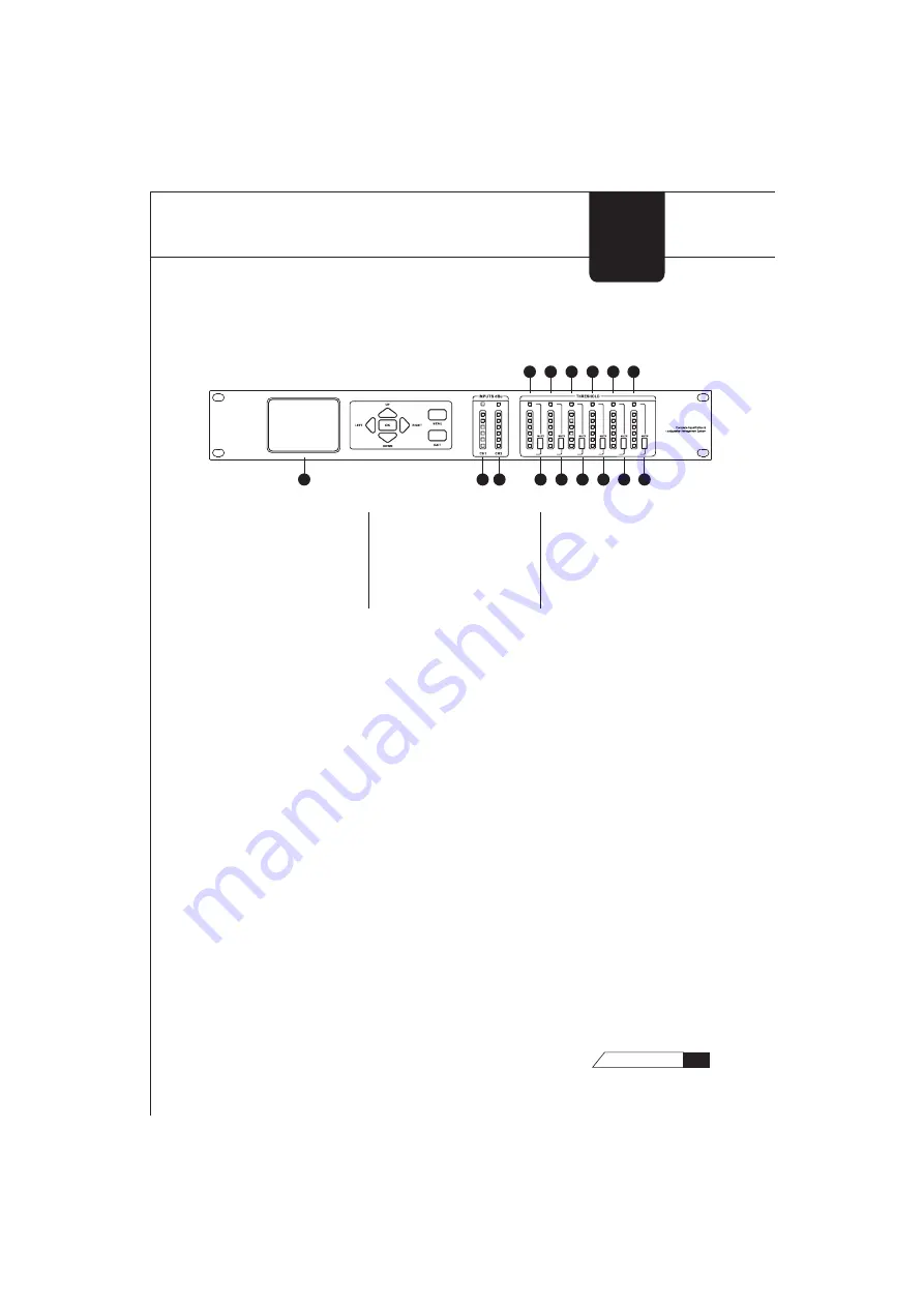
LCD Display
The true color LCD display of the 260™ provides the user with all of the
vital processing information of the 260™ including: signal routing,
configuration modes and effect unit editing.
Function Buttons
The function buttons of the 260™ allow direct access to all editing
functions of the 260™. The buttons include <LEFT>, <RIGHT>, <UP>,
<DOWN>, <MENU>, and < EXIT >. As to their functions, please refer to
Chapter 2.
Input Meters
The 260™ provides the user with two independent, six-segment input
meters that range from -20~ +18 dBu. These meters monitor the signal
level right after the input module.
GETTING
STARTED
1.1Front Panel
1. LCD Display
2. Input Meters 1
3. Input Meters 2
4. Output Mutes 1
5. Output Mutes 2
6. Output Mutes 3
7. Output Mutes 4
8. Output Mutes 5
9. Output Mutes 6
10. Output Meters 1
11. Output Meters 2
12. Output Meters 3
13. Output Meters 4
14. Output Meters 5
15. Output Meters 6
5
260
USER
GUIDE


